

K-WANG
+086-15305925923
Service expert in industrial control field!


Product
Article
NameDescriptionContent
Adequate Inventory, Timely Service
pursuit of excellence


Ship control system
Equipment control system
Power monitoring system
Brand
Product parameters
- Telephone:+86-15305925923
- contacts:Mr.Wang
- Email:wang@kongjiangauto.com
Description
SPECIAL MODELS: MOD001: 6A output contacts instead of 16A.
Notes:
(1) The digit selected for option G must be equal or higher than the digit selected for option F for models including boards 4 and 5.
F1G5 is a valid selection and F5G1 is and invalid selection.
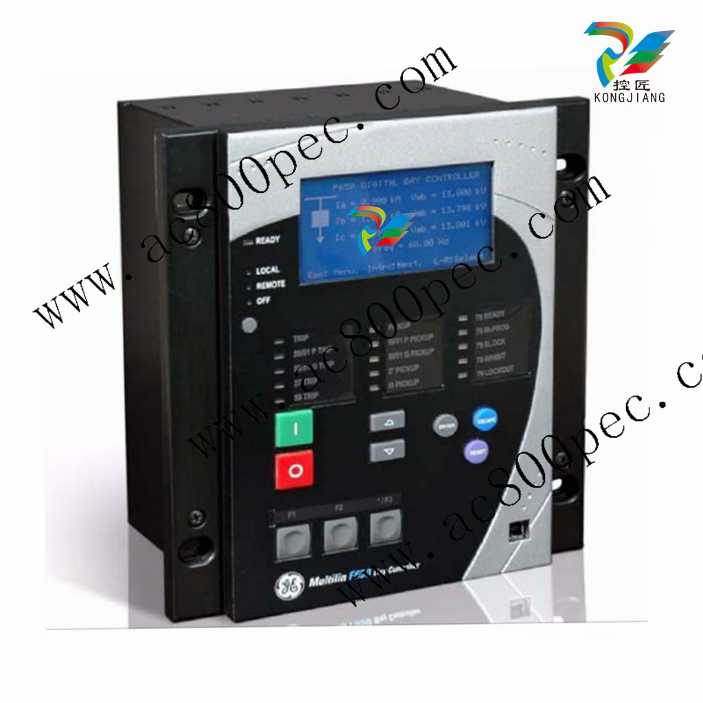
GE F650-M-F-B-4-4-LO-C-6-E Large scale relay protector
NOTE: TECHNICAL SPECIFICATIONS ARE SUBJECT TO CHANGE WITHOUT NOTICE
2.4.1 PROTECTION ELEMENTS
Phase and ground units use as operation magnitude the current value received by the unit in current inputs, while the
neutral unit uses the calculated current value from the three phase currents.
The isolated ground unit will be used only for those applications where the neutral is completely isolated, and it uses the
fifth CT of the unit. This CT has a sensitivity that is 10 times higher than the universal model (connected to 1A or 5A
transformers). Therefore, it does not admit such a high permanent overload.
2.4.1.1 PHASE TIME OVERCURRENT (51PH/51PL)
Current Input Phasor (without harmonics) or RMS
Rated current For connection to 1 or 5 A CTs.
Pickup level 0.05 to 160.00 A in steps of 0.01 A
Dropout level 97% to 98% of the pickup level
Level Accuracy Values at nominal frequency:
±0.5% of the reading ± 10 mA from 0.05 to 10 A
±1.5% of the reading for higher values.
Curve Shapes IEEE extremely / very / moderately inverse
IEC A/B/C/long-time inverse/short time inverse curve
IAC extremely / very / moderately inverse
ANSI extremely / very / normally / moderately inverseI2t
Definite time
Rectifier curve
FlexCurve™ A/B/C/D user curve
Curve Multiplier (Time Dial) 0.00 to 900.00 s in steps of 0.01 s
Reset type Instantaneous or time delayed according to IEEE
Timing accuracy Operate at > 1.03 times the pickup ±3% of operate time or
50 ms. (whichever is greater)
Voltage restraint Selectable by setting
Saturation Level 48 times the pickup level
Snapshot Events Selectable by setting
2.4 TECHNICAL SPECIFICATIONS 2 PRODUCT DESCRIPTION
2.4.1.4 SENSITIVE GROUND TIME OVERCURRENT (51SG)
2.4.1.5 PHASE AND GROUND INSTANTANEOUS OVERCURRENT (50PH/50PL/50G)
Current Input Phasor (without harmonics) or RMS
Rated current For connection to 1 or 5 A CTs.
Pickup level 0.005 to 16.000 A in steps of 0.001 A
Dropout level 97% to 98% of the pickup level
Level Accuracy Values at nominal frequency:
±1.5% of the reading ± 1 mA from 0.005 to 16 A
Curve Shapes IEEE extremely / very / moderately inverse
IEC A/B/C/long-time inverse/short time inverse curve
IAC extremely / very / moderately inverse
ANSI extremely / very / normally / moderately inverseI2t
Definite time
Rectifier curve
FlexCurve™ A/B/C/D user curve
Curve Multiplier (Time Dial) 0.00 to 900.00 s in steps of 0.01 s
Reset type Instantaneous or time delayed according to IEEE
Timing accuracy Operate at > 1.03 times the pickup ±3% of operate time
or 50 ms. (whichever is greater)
Saturation Level 48 times the pickup level
Snapshot Events Selectable by setting
Current Input Phasor (without harmonics) or RMS
Rated current For connection to 1 or 5 A CTs.
Pickup level 0.05 to 160.00 A in steps of 0.01 A
Dropout level 97% to 98% of the pickup level
Level Accuracy Values at nominal frequency:
±0.5% of the reading ± 10 mA from 0.05 to 10 A
±1.5% of the reading for higher values
Overreach < 2%
Trip delay 0.00 to 900.00 s. in steps of 0.01 s.
Reset delay 0.00 to 900.00 s. in steps of 0.01 s.
Operate time <50 ms at 3 x Pickup at 50 Hz, typically
Timing accuracy at 0 ms time delay (no intentional delay): 50ms
at non-zero time delay: ±3% of operate time or 50 ms
(whichever is greater)
Snapshot Events Selectable by setting
2 PRODUCT DESCRIPTION 2.4 TECHNICAL SPECIFICATIONS
2.4.1.6 NEUTRAL INSTANTANEOUS OVERCURRENT (50N)
2.4.1.7 SENSITIVE GROUND INSTANTANEOUS OVERCURRENT (50SG)
Current Input Fundamental Phasor (without harmonics)
Pickup level 0.05 to 160.00 A in steps of 0.01 A
Dropout level 97% to 98% of the pickup level
Level Accuracy Values at nominal frequency:
±0.5% of the reading ± 10 mA from 0.05 to 10 A
±1.5% of the reading for higher values
Overreach < 2%
Trip delay 0.00 to 900.00 s. in steps of 0.01 s.
Reset delay 0.00 to 900.00 s. in steps of 0.01 s.
Operate time <50 ms at 3 x Pickup at 50 Hz, typically
Timing accuracy at 0 ms time delay (no intentional delay): 50ms
at non-zero time delay: ±3% of operate time or 50 ms
(whichever is greater)
Snapshot Events Selectable by setting
Current Input Phasor (without harmonics) or RMS
Rated current For connection to 1 or 5 A CTs.
Pickup level 0.005 to 16.000 A in steps of 0.001 A
Dropout level 97% to 98% of the pickup level
Level Accuracy Values at nominal frequency:
±1.5% of the reading ± 1 mA from 0.005 to 16 A
Overreach < 2%
Trip delay 0.00 to 900.00 s. in steps of 0.01 s.
Reset delay 0.00 to 900.00 s. in steps of 0.01 s.
Operate time <50 ms at 3 x Pickup at 50 Hz, typically
Timing accuracy at 0 ms time delay (no intentional delay): 50ms
at non-zero time delay: ±3% of operate time or 50 ms
(whichever is greater)
Snapshot Events Selectable by setting
2.4 TECHNICAL SPECIFICATIONS 2 PRODUCT DESCRIPTION
2.4.1.8 ISOLATED GROUND INSTANTANEOUS OVERCURRENT (50IG)
2.4.1.9 NEGATIVE SEQUENCE CURRENT (46)
Current Input Fundamental Phasor (without harmonics)
Voltage Input Fundamental Phasor (without harmonics)
Current Pickup level 0.005 to 0.400 A in steps of 0.001 A
Voltage Pickup level 2 to 70 V in steps of 1 V
Dropout level 97 to 98% of the pickup level
Level Accuracy ±1.5% of the reading ± 1 mA from 0.005 to 16 A
Trip delay 0.00 to 900.00 s. in steps of 0.01 s.
Time to instantaneous 0.00 to 900.00 s. in steps of 0.01 s.
Operate time <50 ms at 3 x Pickup at 50 Hz, typically
Timing accuracy at 0 ms time delay (no intentional delay): 50ms
at non-zero time delay: ±3% of operate time or 50 ms
(whichever is greater)
Snapshot Events Selectable by setting
Current Input Fundamental Phasor (without harmonics)
Pickup level 0.05 to 160.0 A in steps of 0.01 A
Dropout level 97% to 98% of the pickup level
Level Accuracy Values at nominal frequency:
±0.5% of the reading ± 10 mA from 0.05 to 10 A
±1.5% of the reading for higher values
Curve Shapes IEEE extremely / very / moderately inverse
IEC A/B/C/long-time inverse/short time inverse curve
IAC extremely / very / moderately inverse
ANSI extremely / very / normally / moderately inverse
Definite time
Rectifier curve
FlexCurve™ A/B/C/D user curve
Curve Multiplier (Time Dial) 0.00 to 900.00 s in steps of 0.01 s
Reset type Instantaneous or time delayed according to IEEE
Timing accuracy Operate at > 1.03 times the pickup ±3% of operate time
or 50 ms. (whichever is greater)
Saturation Level 48 times the pickup level
Snapshot Events Selectable by setting
2 PRODUCT DESCRIPTION 2.4 TECHNICAL SPECIFICATIONS
2.4.1.10 PHASE DIRECTIONAL (67P)
2.4.1.11 GROUND DIRECTIONAL (67G)
2.4.1.12 NEUTRAL DIRECTIONAL (67N)
Directionality Forward and reverse selectable by setting
Polarizing Quadrature Voltage:
ABC seq: Phase A (VBC), Phase B (VCA), Phase C
(VAB)
ACB seq: Phase A (VCB), Phase B (VAC), Phase C
(VBA)
Polarizing voltage threshold 0 to 300 Vac in steps of 1 V
Current Sensitivity Threshold 50 mA
Characteristic angle -90º to +90º in steps of 1º
Block Logic Permission or Block selectable by setting
Angle accuracy ±3º for I>0.1 A and V>5 Vac
Operate time <30ms, typically
Directionality Forward and reverse selectable by setting
Polarizing Voltage, current, dual
Polarizing Voltage VN (measured or calculated, selected by setting)
Polarizing Current Isg (measured from 5th current transformer)
Operating Current Ig (measured from 4th current transformer)
Polarizing Voltage threshold 0 to 300 Vac in steps of 1 V
Polarizing Current threshold 0.005 A
Characteristic angle -90º to +90º in steps of 1º
Block Logic Permission or Block selectable by setting
Angle accuracy ±3º for I>0.1 A and V>5 Vac
Operate time <30ms, typically
Directionality Forward and reverse selectable by setting
Polarizing Voltage, current, dual
Polarizing Voltage VN (measured or calculated, selected by setting)
Polarizing Current Isg (measured from 5th current transformer)
Operating Current IN
Polarizing Voltage threshold 0 to 300 Vac in steps of 1 V
Polarizing Current threshold 0.005 A
Characteristic angle -90º to +90º in steps of 1º
Block Logic Permission or Block selectable by setting
Angle accuracy ±3º for I>0.1 A and V>5 Vac
Operate time <30ms, typically
Purchase history
| User name | Member Level | Quantity | Specification | Purchase Date |
|---|
Total 0 Record
Related products

Customer Reviews
Satisfaction :
5 Stars
No evaluation information


- LTI Drives
- other
- ADLINK
- Beckhoff
- Shinkawa
- Other Brands
- AMAT
- Iba
- PEPPERL+FUCHS
- Aerotech
- WATLOW
- MAN
- ADVANCED
- Abaco
- YOKOGAWA
- KOLLMORGEN
- MEGGITT
- kong-sberg
- METSO
- Motorola
- NI
- OEMAX
- RELIANCE
- scanlab
- schneider
- uniop
- Vibro-Meter
- Honeywell
- Rolls-Royce
- MOOG
- GE
- B&R
- Woodward
- Yaskawa
- xYCOM
- Siemens
- Emerson
- HIMA
- Bently
- ZYGO
- FOXBORO
- OMACO
- PROSOFT
- ENTERASYS
- TRICONEX
- Parker
- Lenze
- KEBA
- Alstom
- CTI
- ABB
- A-B
145

-
 ENOTEC Integrated Products
 -
 ENOTEC OXITEC ® 500E Extraction Oxygen Analyzer
 -
 KUKA KR CS Box-2 Compact Controller for Four Axis SCARA Robot
 -
 KUKA KR C5 slim-2 Robot Controller
 -
 KUKA KR C5 micro With KUKA System Software (KSS/VSS) Assembly Instructions
 -
 KUKA KR C5 micro controller
 -
 KUKA KR C5 Controller Assembly Instructions
 -
 KUKA KR C5 compactcab and KR C5 small-size cab cabinets
 -
 KUKA KR C4 smallsize-2 small robot control cabinet
 -
 KUKA KR C4 Midsize/KR C4 Midsize CK Assembly Manual
 -
 ENOTEC ® Installation and Operation Instructions for 5000/5000+Oxygen Analyzer System
 -
 KUKA KR C4 extended; KR C4 extended CK Assembly Instructions Assembly Manual
 -
 Assembly/Installation Manual for KUKA KR C4 Compact Control Cabinet
 -
 KUKA Sunrise Cabinet Med Medical Collaborative Robot Special Control Cabinet
 -
 KUKA Sunrise Cabinet Next Generation Small Control Cabinet
 -
 KUKA KR C4 Smallsize-2 family's smallest control cabinet
 -
 KUKA KR C4 midsize; KR C4 midsize CK medium-sized control cabinet
 -
 KUKA KR C4 extended is a high-power multi axis control cabinet
 -
 General installation and operation instructions for KUKA KR C4 and KR C4 CK controllers
 -
 KUKA KR C4 compact controller operation instructions
 -
 Installation and Operation Instructions for KUKA Robot Arm
 -
 KUKA TITAN-2 Ultra Ground Overloading Six Axis Robot
 -
 Assembly instructions for KUKA KR SCARA-2 CS series robotic arm body
 -
 KUKA MA KR SCARA X Installation Guide
 -
 KUKA KR FORTEC-2 Ultra Heavy duty Ground Six Axis Robot Mechanical Assembly Manual
 -
 KUKA KR FORTEC-2 new generation heavy-duty ground six axis robot
 -
 KUKA Robots KR 1000 titan; KR 1000 L750 titan With F Variants Assembly Instructions
 -
 KUKA KR 600 FORTEC heavy-duty six axis ground mounted industrial robot
 -
 KUKA KR 500 MT FORTEC Heavy duty Six Axis Industrial Robot
 -
 KUKA KR 360 FORTEC Heavy duty Six Axis Industrial Robot
 -
 KUKA Sunrise Cabinet Med Medical Edition Robot Controller User Manual
 -
 KUKA Robots KR SCARA HO Assembly Instructions
 -
 KUKA Robots KR QUANTEC-2 PA Assembly Instructions
 -
 KUKA Robots KR QUANTEC-2 K and KR QUANTEC-2 P With K-F and P-C Variants Assembly Instructions
 -
 KUKA Robots KR QUANTEC-2 HO Assembly Instructions
 -
 KUKA Robots KR QUANTEC-2 HC Assembly Instructions
 -
 KUKA KR QUANTEC-2 series heavy-duty ground mounted six axis industrial robot
 -
 KUKA KR QUANTEC PA series heavy-duty palletizing robot
 -
 KUKA KR IONTEC-2 series six axis industrial robot
 -
 KUKA KR IONTEC ultra series six axis heavy-duty industrial robot
 -
 KUKA KR IONTEC HO Robot Assembly Manual
 -
 KUKA Robots KR CYBERTECH-3 HW Assembly Instructions
 -
 KUKA Robots KR CYBERTECH-3 Assembly Instructions
 -
 KUKA Robots KR CYBERTECH-2 arc Assembly Instructions
 -
 KUKA Robots KR CYBERTECH nano-2 Assembly Instructions
 -
 KUKA KR CYBERTECH CR HO (KR 20 R1810-HO) assembly instructions
 -
 KUKA Robots KR CYBERTECH With F variant Assembly Instructions
 -
 KUKA KR CYBERTECH CR (KR 20 R1810-CR) Clean Room (CR) Version 6-Axis Industrial Robot
 -
 KUKA KR AGILUS-3 ultra series small six axis serial robot
 -
 KUKA KR 300 R2700-2 C-F Cast Ceiling Mounted 6-Axis Heavy duty Industrial Robot
 -
 KUKA KR 20 R1820-2 E Six Axis Industrial Robot
 -
 Assembly instructions for KUKA KR AGILUS-3 small six axis robot
 -
 KUKA KR AGILUS-2 New Generation Small Six Axis Robot
 -
 KUKA KR 1000 1300 titan PA; KR 1000 L950 titan PA With F Variants Assembly Instructions
 -
 KUKA KR 700 PA/KR 700 PA Arctic Installation Guide
 -
 KUKA KR 18 R1450-3 PP six axis ground mounted industrial robot
 -
 KUKA 12 SCARA Series 4-axis SCARA Horizontal Joint Robot
 -
 KUKA KR 4 R600 Small Six Axis Industrial Robot
 -
 Installation Guide for KUKA KR 3 R540 Small 6-Axis Industrial Robot
 -
 KUKA LBR iiwa CR Clean 7-Axis Lightweight Collaborative Robot
 -
 KUKA KR AGILUS sixx series six axis industrial robot operation instructions
 -
 KUKA 4-axis heavy-duty SCARA horizontal multi joint robot KR 60 R1200 Z400 CS
 -
 KUKA KR 23 SCARA-2 CS SCARA Horizontal Multi Joint Robot
 -
 KUKA KR 20 SCARA CS Robot Assembly Instructions
 -
 KUKA KR 15 DELTA-2 Assembly Manual
 -
 KUKA KR 13 SCARA-2 CS Assembly Manual
 -
 KUKA KR 3 D1200 (Standard Delta Robot) Assembly Instructions
 -
 KUKA KR 3 D1200 HM Assembly Manual
 -
 KUKA LBR Med 7 R800, LBR Med 14 R820 Medical Edition Robot
 -
 KUKA Robots LBR iiwa 7 R800, LBR iiwa 14 R820 Operating instructions
 -
 KUKA LBR iiwa CR (Clean Room Version Robot) Operating Instructions
 -
 Lauer PCStopline series text operation panel
 -
 KUKA LBR iisy (MA_LBR_iisy V5) assembly manual
 -
 KUKA LBR iisy 3 R760 Assembly Manual
 -
 KUKA LBR iico Collaborative Robot Assembly Manual
 -
 Lauer LCAstarline (LCA300/LCA320/LCA325) Text Display Screen
 -
 Lauer PCS950/PCS950c/PCS950e operation console
 -
 Lauer EPC Series Industrial Embedded Human Computer Integrated PC User Guide
 -
 Bonfiglioli Precision Planetary Gearbox TIR-STD ENG R07
 -
 Bonfiglioli ACT/ACU Cold Plate Inverter Installation Instructions
 -
 Bonfiglioli EM-RES-02 Expansion Module
 -
 Bonfiglioli EM-RES-01 Expansion Module
 -
 Bonfiglioli EM-IO-04 Expansion Module
 -
 Bonfiglioli EM-IO-03 Expansion Module
 -
 Bonfiglioli EM-IO-02 Expansion Module
 -
 Bonfiglioli Vectron EM-IO-01 Expansion Module
 -
 Bonfiglioli F series gearbox
 -
 Installation, operation, maintenance, and spare parts of Bonfiglioli HF series reducers
 -
 Installation, Operation, and Maintenance of Bonfiglioli 300-300M Series ATEX Reducer
 -
 Bonfiglioli R3 series planetary gearbox
 -
 Bonfiglioli C series inline helical gear explosion-proof reducer
 -
 Bonfiglioli EM-ENC-05 Expansion Module
 -
 Bonfiglioli EM-ENC-04 Expansion Module
 -
 Bonfiglioli EM-ENC-03 Expansion Module
 -
 Bonfiglioli EM-ENC-02 Expansion Module
 -
 Bonfiglioli CM-CAN CANopen communication module
 -
 Bonfiglioli EM-SYS System Bus Expansion Module
 -
 Bonfiglioli CM-PDP Profibus DP Communication Module
 -
 Bonfiglioli CM-232/CM-485/CM-485T Modbus Communication Manual
 -
 Bonfiglioli BMS series precision planetary servo reduction motor
 -
 Bonfiglioli ACTION series ACT210 (230V), ACT410 (400V) frequency converter operation manual
 -
 Bonfiglioli ACT series frequency converter
 -
 Bonfiglioli HDP/HDO series gear unit IOM installation, operation and maintenance instructions
 -
 Installation, operation, and maintenance of Bonfiglioli 300-300M series reducers
 -
 Bonfiglioli 300M Modular planetary gearboxe
 -
 Bonfiglioli 3/H series heavy-duty modular gearbox
 -
 Bonfiglioli KRG-KCG-KSD hydraulic coupling
 -
 Bonfiglioli Vectron BTD-BCR servo motor
 -
 Bonfiglioli BTD-BCR synchronous servo motor
 -
 Bonfiglioli VF-W series ATEX explosion-proof worm gear reducer
 -
 Bonfiglioli EM-ENC-03 Expansion Module
 -
 Installation, operation, maintenance, and spare parts instructions for Bonfiglioli EVOX-CP series helical gear reducers (including ATEX explosion-proof models)
 -
 Installation, operation, and maintenance IOM instructions for Bonfiglioli C/A/F/S series gear reducers (including ATEX explosion-proof versions)
 -
 Bonfiglioli BX-BE-BN-MX-ME-BXN-MNN Motor Installation, Operation and Maintenance Manual
 -
 Bonfiglioli VF-W IE2-IE3 Worm Gear Reduction Motor: Complete Selection, Verification, and On site Implementation Technical Guide
 -
 Bonfiglioli VF-W series ATEX worm gear reducer
 -
 Bonfiglioli RAN series bevel gear angle reducer
 -
 Bonfiglioli Industry&Automation Business Unit Integrated Products
 -
 Bonfiglioli EVOX platform CP coaxial helical gear reduction motor
 -
 Bonfiglioli C-A-F-S Series IE2-IE3-IE4 three series reducers
 -
 Complete selection, calibration, and common selection of Bonfiglioli C-A-F industrial gear units
 -
 Bonfiglioli C series explosion-proof helical gear reducer
 -
 Bonfiglioli BN-BE-BX-BY series three-phase asynchronous motor
 -
 Bonfiglioli BMD series permanent magnet AC synchronous servo motor
 -
 Bonfiglioli A-series spiral bevel gear right angle servo reduction motor
 -
 Installation, Operation, and Maintenance Instructions for Bonfiglioli AS Series Reducer
 -
 Bonfiglioli Active series high-end frequency converter
 -
 Bonfiglioli EM-IO-04 Expansion Module

K-JIANG

Add: Jimei North Road, Jimei District, Xiamen, Fujian, China
Tell:+86-15305925923