
K-WANG


- Telephone:+86-15305925923
- contacts:Mr.Wang
- Email:wang@kongjiangauto.com
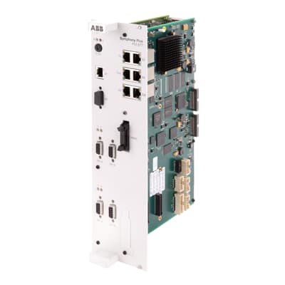
PM 877, Controller1 x Onet, 1 x red. Cnet (C), 2 x red. Fnet, 2 x DPV2, 1 x Eth- with current SW version- up-, downgrade of FW via USB-Stick or Analyzer possible- PROFIBUS DP release only with License !- Redundancy Link Cable NT 031 necessary for redundantcontroller
ABB PM877 3BDH000777R1 Central_Unit Controller
The AC 800M controller consists of a selection of units mounted on horizontal
DIN-rails, which can be housed within an enclosure. The majority of units consist of
a base mounting plate and a removable module attached with screws.
The hardware units that form the AC 800 M controller are:
• Central Processor unit (CPU)
• Communication interface modules for different protocols
• S800 I/O modules
• Power supply modules
Various I/O systems can be connected to the AC 800M controller, either directly
(S800 I/O) or via PROFIBUS or FOUNDATION.
Figure 1. Example of an AC 800M Controller with an S800 I/O Unit
The CPU consist of a base plate TP830 (Terminal Plate) and a processor module
PM8XX with various speed and memory combinations.
The base plate TP830 carries the majority of the connections to processor, the power
supplies and communication interfaces, as well as to external buses.
Communication Interface
A number of communication modules can be connected to the controller. See
Appendix A, IndustrialIT System 800xA AC 800M Controller - Data Sheet for
more information on the various modules.
Communication Interface connected with CEX bus:
Up to 12 communication units can be placed on Communication Expansion Bus
(CEX) bus.
The CEX bus must be terminated if a communication unit is connected. A CEX bus
termination is delivered with the e CPU: tb850 (male) or TB851 (female).
An extension cable TK850 with connector DB25P with metal housing and a length
of 0.7meter (1.3') can be used for extending the CEX bus to a second din rail.
S800 I/O
S800 I/O is a distributed and modular I/O system that communicates with
controllers over PROFIBUS-DP/DPV1 or direct (via Modulebus).
The S800 I/O system is DIN rail mounted and consists of Fieldbus Communication
Interfaces, Modulebus Modems, S800 I/O modules and Module Termination Units
(MTU). S800 I/O modules (not S800L) are mounted on MTU's, this makes them
hot-swappable. Depended on the mounting requirement (horizontal or vertical) and
on the field termination needs (powering, fusing etc.) there are numerous of MTU's
to choose from.
The S800 I/O system supports fully redundant applications, redundancy can be built
in on both communication level and I/O module level.
S800 I/O connected with PROFIBUS- DP/DPV1:
• Field Communication Interface CI801 or CI840 is the I/O station master
• Maximum 24 I/O modules per I/O station
• 1 base I/O cluster with up to 12 I/O modules (connected via electrical
Modulebus)
• 1-7 additional I/O clusters with up to 12 I/O modules per cluster (connected via
optical Modulebus using Modulebus Modems)
Mounting AC 800M and S800 I/O Units onto DIN-Rail
AC 800M and S800 I/O units are DIN-rail mountable. Each unit has a DIN rail
locking mechanism that achieve mechanical locking and effective grounding.
The additional screw lugs, located in the lower part of the units are used to provide
extra fastening in environments subject to excessive vibrations. AC 800M units
(CPU and communication interfaces) must be mounted on horizontal DIN rails.
S800 I/O units can be mounted on both horizontal and vertical DIN rails.
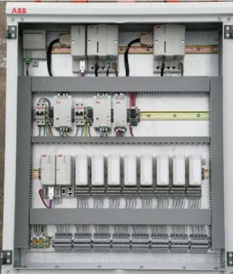
There are two ways of mounting AC 800M and S800 I/O in cabinets, open rack or
other types of installations:
• Mounting on DIN rail attached to a metal sheet
• Mounting on prefabricated aluminium profile with DIN rail
All conductive structural components of the installation must be bonded together
with good and permanent connections for electrical safety and EMC reasons.
The bonding should preferably be made with self-tapping cutting head screws.
On painted surfaces where fastening is done by screw and nut, the paint must be
removed from the contact surfaces. Apply conductive grease on surfaces to ensure a
permanent connection. The cabinet/rack shall be properly connected to protective
earth/ground.
Mechanical Installation - Metal Sheet
The DIN-rail is mounted on an unpainted metal sheet with fastening screws every
100 mm to ensure good mechanical stability and a good chassis ground connection
in the cabinet or an open rack, see Figure 3.
There are aluminum profiles for horizontal and vertical mounting. The aluminum
profile gives an excellent grounding and rigid mounting of products concerned.
The aluminum profile shall be fastened to the cabinet with at least 4 self-tapping
screws.
The profile has grooves for screws that can be used for fastening the modules in an
environment with excessive vibrations.
The aluminum profiles have one DIN-rail and one cable duct
| User name | Member Level | Quantity | Specification | Purchase Date |
|---|


- other
- ADLINK
- LTI Drives
- Other Brands
- AMAT
- Iba
- PEPPERL+FUCHS
- Aerotech
- WATLOW
- MAN
- ADVANCED
- Abaco
- YOKOGAWA
- KOLLMORGEN
- MEGGITT
- kong-sberg
- METSO
- Motorola
- NI
- OEMAX
- RELIANCE
- scanlab
- schneider
- uniop
- Vibro-Meter
- Honeywell
- Rolls-Royce
- MOOG
- GE
- B&R
- Woodward
- Yaskawa
- xYCOM
- Siemens
- Emerson
- HIMA
- Bently
- ZYGO
- FOXBORO
- OMACO
- PROSOFT
- ENTERASYS
- TRICONEX
- Parker
- Lenze
- KEBA
- Alstom
- CTI
- ABB
- A-B

-
 DEIF PPU 300 controller
 -
 DEIF Delomatic 4 Offshore/Ocean Platform Dedicated Generator Power Management System DM-4
 -
 DEIF Delomatic Modular Generator Set Integrated System
 -
 DEIF AGC-4 Mk II Generator Set Controller
 -
 DEIF AGC-4 diesel generator set integrated controller
 -
 DEIF Multi line 2 Series PPU Unit Power Management (PPM) Operation Manual
 -
 DEIF Multi line 2 V2.4X Installation Manual
 -
 Beckwith M-6280 Digital Capacitor Bank Controller
 -
 Beckwith M-3311 Transformer Protection Relay
 -
 Beckwith M-3311A Transformer Integrated Protection Device
 -
 Beckwith M-3310 Transformer Integrated Protection Device Specification
 -
 Beckwith M-0359 Syncrocloser Check Plus Application Guide for Synchronous Calibration Relay
 -
 Beckwith M-0293A On Load Tap changer Controller Application Guide
 -
 DEIF GPU-3 Synchronous/Asynchronous Generator Integrated Microcomputer Protection Controller
 -
 Installation Instructions for DEIF PPM-3
 -
 Beckwith M-3520 distributed power grid connected comprehensive protection device
 -
 Beckwith M-3430 generator comprehensive protection device
 -
 Beckwith M-2293B adapter panel
 -
 Beckwith M-2001C digital on load voltage regulator controller
 -
 Beckwith M-2001B Digital On Load Voltage Regulating Controller
 -
 Beckwith M-0388/M-0389 synchronous verification relay
 -
 Beckwith M-0193B synchronous closing device
 -
 Beckwith M-0115A Transformer Parallel Balancing Module
 -
 Beckwith M-0067E on load tap changer controller
 -
 Beckwith M-4272 Digital Motor Bus Switching System
 -
 Beckwith M-3311A Transformer Integrated Protection Device
 -
 Beckwith M-3425A Generator Integrated Protection Device Manual
 -
 Basler BE1-27/BE1-59/BE1-27/59 undervoltage/overvoltage relay
 -
 Basler AVC63-12/AVC125-10 excitation voltage regulator
 -
 Basler L301kc Color Three Line Array Camera Operation Manual
 -
 Basler CBS 212A Current Enhanced Excitation System
 -
 Basler BE3-25 synchronous check relay
 -
 Operation Manual for Basler BE1-32R/BE1-32O/U Direction Power Relay
 -
 Basler Electric PRS-250 Veri Sync Synchronous Relay
 -
 Basler Pilot Series Area Array Industrial Camera piA2400-17gc
 -
 Basler BE1-11g comprehensive protection device for generator
 -
 Basler VR63-4C/UL Analog Excitation Voltage Regulator
 -
 Basler BE1-DFPR distribution feeder protection relay
 -
 Basler CBS310/CBS320 current strong excitation system
 -
 Basler UFOV250A/UFOV260A Low Frequency Overvoltage Module
 -
 Basler MVC104/MVC108/MVC232 manual voltage control device
 -
 Basler XR2002/XR2002F PMG excitation regulator
 -
 Basler DECS-400 Digital Excitation Control System
 -
 Basler DGC-2020 Digital Generator Set Controller
 -
 Basler MVC-300 Electronic Manual Excitation Controller
 -
 Basler MVC-104/MVC-108/MVC-232 manual excitation controller
 -
 Basler SSR32-12/SSR63-12/SSR125-12 Static Excitation Voltage Regulator
 -
 Basler SR4A/SR8A Analog Excitation Voltage Regulator
 -
 Basler BE2000E Digital Excitation Voltage Regulator
 -
 Basler DECS-2100 Digital Excitation System
 -
 Basler BE1-851 Overcurrent Protection Device Manual
 -
 Basler APR 63-5 Voltage Regulator
 -
 Basler BE1-FLEX Integrated Protection Control System
 -
 Basler BE1-700V digital voltage protection relay
 -
 Basler BE1-87B high impedance bus differential relay
 -
 Basler BE1-40Q demagnetization relay
 -
 Basler BE1-60 Voltage Balance Relay
 -
 Basler BE1-47N negative sequence voltage phase sequence relay
 -
 Basler BE1-81O/U digital frequency relay
 -
 Basler BE1-11f Feedline Integrated Protection Device Manual
 -
 Basler DECS-250 Digital Excitation Control System
 -
 Basler DECS-100 Digital Excitation Control System
 -
 Basler BE1-BPR Circuit Breaker Protection Relay
 -
 Basler BE1-50/51B-255 overcurrent relay
 -
 Basler BE1-25 synchronous check relay
 -
 Basler BE1-51 microcomputer time limited overcurrent relay
 -
 Basler DECS-300 Digital Excitation Control System
 -
 Mitsubishi MELSEC-F FX series programmable controllers
 -
 Hirschmann cSCALE Mobile Machinery Modular Controller
 -
 Hirschmann OZD Profi G12DU/G12DK/G12DE ATEX1 PROFIBUS Fiber Optic Repeater Manual
 -
 Hirschmann OCTOPUS OS20/OS24 Network Managed IP65/IP67 Industrial Switch Installation Manual
 -
 Hirschmann RS20/RS22/RS30/RS32/RS40 Series Industrial Rail Switch Installation Manual
 -
 Hirschmann EAGLE One Industrial Ethernet Firewall Installation Manual
 -
 Hirschmann MACH102 Series Industrial Switch Installation Manual
 -
 Hirschmann MS20/MS30 Modular Industrial Switch Installation Manual
 -
 Hirschmann BRS20/22/30/32/40/42/50/52 Series BOBCAT Industrial Rail Switch Installation Manual
 -
 Hirschmann RSB20 Basic Series Industrial Rail Switch Installation Manual
 -
 Hirschmann RS20 Basic Series Industrial Ethernet DIN-Rail Switches
 -
 BECKHOFF EP20xx/EP28xx IP67 EtherCAT Box Digital Output Module
 -
 BECKHOFF EL5102 Incremental Encoder Terminal Manual
 -
 BECKHOFF CU8803-000x CP Link4 Launch Box Operation Manual
 -
 Beckhoff CU20xx/CU22xx Industrial Unmanned Switch Manual
 -
 BECKHOFF AMP8000 Distributed Servo System Operation Manual
 -
 BECKHOFF EL2911/EL2911-2200 TwinSAFE Safety Potential Supply Terminal Manual
 -
 BECKHOFF EL600x/EL602x series EtherCAT serial port terminal module
 -
 BECKHOFF CP6700-0001-0050/0060 Integrated Machine Manual
 -
 BECKHOFF CP70xx Series Control Panel Installation and Operation Manual
 -
 BECKHOFF CP29xx Cabinet Mounted Industrial Touch Panel Official Operation Manual
 -
 Beckhoff C6650-0060 Control Cabinet Industrial PC
 -
 Beckhoff BK series K-bus to EtherCAT coupler
 -
 Beckhoff CX20x0 Series Embedded Industrial Control Computer Manual
 -
 Beckhoff CP77xx Series Industrial Panel PC Installation and Operation Manual
 -
 Beckhoff EL41xx Series 16 Bit Analog Output Terminal Manual
 -
 Beckhoff C63xx-0020 series control cabinet industrial PC
 -
 Beckhoff C6920-0060 Control Cabinet Industrial PC
 -
 Beckhoff CU8800-0010 USB transmitter extender (TX)
 -
 Beckhoff AX2000 series digital servo amplifier
 -
 Beckhoff AX8000 Modular Multi Axis Servo System
 -
 Beckhoff CP27xx Embedded Panel PC User Manual
 -
 Beckhoff CP69xx Industrial Embedded Control Panel
 -
 Beckhoff CP60xx Embedded Industrial Control Panel
 -
 Beckhoff CP72xx series panel PC official installation, operation, configuration, maintenance, and troubleshooting
 -
 Installation and Operation of Beckhoff CP78xx Series Control Panel
 -
 Beckhoff CP39xx series industrial touch control panel
 -
 Beckhoff CX8110 Embedded Industrial PC
 -
 Beckhoff CX50x0 series DIN rail embedded industrial PC
 -
 Beckhoff CP62xx series embedded panel PC
 -
 BECKHOFF C6030 Compact Industrial PC
 -
 UniOP ePAD32B/ePAD33B/ePAD33BT Industrial HMI
 -
 UniOP ePAD05&ePAD06 Industrial HMI
 -
 UniOP ePAD03/ePAD04 entry-level HMI
 -
 UniOP CP01R-04 Compact Industrial HMI
 -
UniOP BKDR-16 Industrial Human Machine Interface
-
 Beckwith M-3425A Generator Integrated Protection Relay
 -
 Basler DECS-200 Digital Excitation Control System
 -
 Basler DECS-250 Digital Excitation Control System Manual
 -
 HA-800 series AC servo drive
 -
 JUMO dTRANS p35 Pressure Sensor Operation Manual with IO Link Interface
 -
 KEBA XE 020 RFID Module
 -
 Honeywell SmartLine series transmitters
 -
 Eaton CROUSE-HINDS MTL MA30 RF and Surge Protector Operation Manual
 -
 Beckhoff EL31xx Series 16 Bit EtherCAT Analog Input Terminal Manual
 -
 BECKHOFF AX5000 series EtherCAT servo drive
 -
 BECKHOFF EL30xx Series 12 Bit Analog Input Terminal Manual
 -
 Beckhoff EL70x7 series stepper motor EtherCAT terminal manual
 -
 BECKHOFF CX52x0 Series Embedded Industrial PC Hardware Manual
 -
 BECKHOFF CX9000/CX9010 series embedded controllers
 -
 BECKHOFF AM8000/AM8500 Series Synchronous Servo Motor Operation Manual

K-JIANG

Add: Jimei North Road, Jimei District, Xiamen, Fujian, China
Tell:+86-15305925923