

K-WANG
+086-15305925923
Service expert in industrial control field!


Product
Article
NameDescriptionContent
Adequate Inventory, Timely Service
pursuit of excellence


Ship control system
Equipment control system
Power monitoring system
Brand
Product parameters
- Telephone:+86-15305925923
- contacts:Mr.Wang
- Email:wang@kongjiangauto.com
Description
Features:
Up to 1.26 GHz PentiumIll processor with 512 Kbyte
advanced transfer cache
Up to 512 Mbyte PC133 SDRAM using a single SODIMM
Internal AGP SVGA controller with 4 Mbyte display cache
133 MHz system bus via lntel®815E chipset
Dual Ethernet controllers supporting 10BaseT and 100BaseTX
interfaces
Remote Ethernet booting
PMC expansion site
Operating system support for Windows XP, Windows 2000,
VxWorks, Solaris™, QNX,LynxOS,and Linux
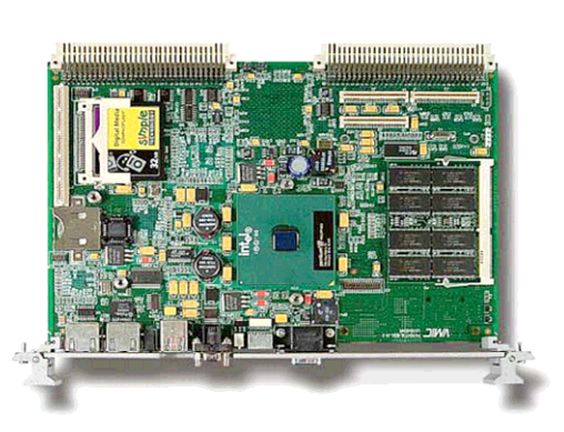
GE VMIVME-7750 VME Single Board Computer
DRAM Memory: The VMIVME-7750 accepts one 144-pin SDRAM
SODIMM for a maximum memory capacity of 512 Mbyte. The
DRAM is dual ported to the VME.
BIOS: System and video BIOS are provided in reprogrammable
flash memory.
Super VGA Controller: High resolution graphics and
multimedia-quality video are supported on the VMIVME-7750 by
a built-in 815E chipset AGP graphics adapter. The adapter is
complemented by 4 Mbyte external synchronous DRAM cache
with a high-bandwidth 64-bit data interface. Screen resolutions
up to 1,600 x 1,200 x 256 colors (single view mode) are
supported by the graphics adapter.
Table 1. Partial List of Display Modes Supported
A = Processor
2 = 733 MHz Pentium III (Extended Temperature Range: 0 to 60º C)
3 = 733 MHz Pentium III
4 = 866 MHz Pentium III
5 = Reserved
6 = 1 GHz Pentium III (0 to 40° C)
7 = 1.26 GHz Pentium III with 512 Kbyte Cache
8 = Reserved
9 = Reserved
G = 733 MHz Pentium III with Fansink (0 to 40° C)
B = SDRAM Memory
2 = Reserved
3 = 64 Mbyte
4 = 128 Mbyte
5 = 256 Mbyte
6 = 512 Mbyte
C = CompactFlash
1 = Reserved
4 = 64 Mbyte
5 = Reserved
6 = 128 Mbyte
8 = Reserved
9 = 256 Mbyte
G = 512 Mbyte
H = 1 Gbyte
D = 0 (Option reserved for future use)
E = 0 (Option reserved for future use)
F = Special Sales Order
0 = VME Standard
1 = 1101.10 Front Panel
The VMIVME-7750 supports high throughput DMA transfers of
bytes, words, and longwords in both master and slave
configurations.
If endian conversion is not needed, we offer a special “bypass”
mode that can be used to further enhance throughput. (Not
available for byte transfers.)
Master Interface: MA32:MBLT32:MBLT64
(A32:A24:A16:D32:D16:D8 (EO):BLT32)
The VMEbus master interface provides nine separate memory
windows into VMEbus resources. Each window has separate
configuration registers for mapping PCI transfers to the VMEbus
(that is, PCI base address, window size, VMEbus base address,
VMEbus access type, VMEbus address/data size, etc.). The
maximum/minimum window sizes for the nine windows are as
follows:
Window Minimum Size Maximum Size
0, 4 4 Kbyte 4 Gbyte
1 to 3, 5 to 7 64 Kbyte 4 Gbyte
Special Cycle 64 Mbyte 64 Mbyte
Slave Interface: Memory Access
SAD032:SD32:SBLT32:SBLT64
(A32:A24:A16:D32:D16:D8 (EO): BLT32)
The VMEbus slave interface provides eight separate memory
windows into PCI resources. Each window has separate
configuration registers for mapping VMEbus transfers to the PCI
bus (that is, VMEbus base address, window size, PCI base
address, VMEbus access type, VMEbus address/data size, etc.).
The maximum/minimum window sizes for the eight windows
are as follows:
Window Minimum Size Maximum Size
0, 4 4 Kbyte 4 Gbyte
1 to 3, 5 to 7 64 Kbyte 4 Gbyte
In addition, each window can be programmed to operate in
coupled or decoupled mode. In decoupled mode, the window
utilizes a write-posting FIFO and/or a read prefetching FIFO for
increased system performance. In coupled mode, the FIFOs are
bypassed and VMEbus transactions are directly coupled to the
PCI bus (that is, transfers on VMEbus are not completed until
they are completed on the PCI bus).
Enhanced Bus Error Handling: Enhancements over the
Universe chip’s bus error handling features are provided. A latch
and register are provided to allow the SBC to read the VMEbus
address that caused the bus error in all modes. The Universe
chip’s support is limited to decoupled mode.
Support for bus cycle timeout and assertion of bus error is
provided. The board may be configured to assert bus error upon
timeout regardless of its status as system controller. The
Universe chip asserts bus error only if it is system controller. In
addition, this board may be configured to assert an interrupt
upon bus cycle timeout.
Operating System and Software Support
The VMIVME-7750 provides embedded features beyond PC/AT
functionality. These features are supported by GE Fanuc
Embedded Systems software products aimed at developers
who are incorporating GE Fanuc Embedded Systems SBCs, I/O
boards, and workstations into systems. Windows XP/Windows
2000 and VxWorks are the most common operating systems
supported by GE Fanuc Embedded Systems software products.
Windows XP/Windows 2000: The IOWorks® software family is a
set of software components that can work together or
separately to provide a total development environment for any
application in a Windows XP/ Windows 2000 OS.
VMISFT-9422 VMEbus Access™ for Windows XP/Windows
2000: The VMEbus Access product is specifically designed for
accessing the advanced VMEbus Access architecture of the
VMIVME-7750. Running on Windows XP/Windows 2000, VMEbus
Access is both sophisticated and easy to use.
The function library, VMEbus toolset and open architecture
VMEbus Access offers make it one of the most powerful
products on the market today. It provides compatibility with
existing GE Fanuc Embedded Systems VME PC platforms and
compatibility within the future VME PC platforms GE Fanuc
Embedded Systems creates.
The VMEbus Access development package gives you everything
you need to develop applications for your VME operations. This
package includes the VMEmanager™ function library and four
utilities that enable you to easily configure a VMEbus,
dynamically monitor VMEbus activities, manage VMEbus data,
and use DDE-client applications.
VMEbus Access provides powerful tools for developing,
debugging and monitoring VMEbus applications and increasing
VMEbus performance. The flexible design of VMEbus Access
enables you to incorporate it as a standalone solution or use it
to open your VMEbus operations to the IOWorks product suite.
VMEbus Access manipulates the hardware behind the scenes.
With VMEbus Access, you can develop applications in or use
existing applications developed in most programming
environments. For example, VMEbus Access enables your
VMEbus to recognize applications developed in these popular
programming environments:
• IOWorks Manager™
• LabVIEW
• Citect
• Wonderware InTouch
• Visual IOWorks®
• Visual Basic®
Visual C++®
d
•
VxWorks OS Support — VMISFT-7418 Board Support Package:
The VMISFT-7418 is a Wind River Systems, Inc.’s certified board
support package (BSP) for GE Fanuc Embedded Systems’ series
of VME Pentium processor-based computers, which is require
to run the VxWorks OS. With the SBC, VxWorks, the BSP, and
other VME equipment from GE Fanuc Embedded Syste
implementations can be created for a wide variety of
applications, including real time factory automation, sim
instrumentat
ms,
ulation,
ion and control, and process control and
ware
nuc
rts,
ards. The
e
as
.
ture
g-endian and little-endian devices to
us
g
r
7xxx SBC boards without requiring any
ge:
ilitary
aris OS provides POSIX ivers
s
ent based on industry-wide
rted I/O board and new
uc
; or
ications
6U
.3mm)
m
2 and -12VDC are specified with the
operating temperature is available for the following
C)
measured at outside of heatsink is to be
%, noncondensing
rfa
(3 to 0), ROR, RWD, BCAP
dle
r: , IRQ7* to IRQ1*
r:
le (4 to 1,024 µs)
signaling, types 1 and 2
TBF: 118,633 hours (Bellcore)
monitoring.
The BSP is linked with VxWorks OS, thus allowing soft
applications created with Wind River Systems, Inc.’s
development system to load and run on the particular GE Fa
Embedded Systems SBC hardware being used. Serial po
parallel ports, keyboard, text mode video, and Ethernet
transceivers are all supported, as well as floppy and IDE hard
disk drives that can be connected to the computer bo
BSP provides Flash boot, NVRAM and timer support.
The BSP allows VxWorks applications to have access to th
VMEbus. When hardware includes single cycle and block
transfers using DMA devices, they are supported by the BSP,
are interprocessor communications with mailbox registers.
VMEbus interrupt handling and error handling are supported
Since the VMEbus environment often contains a mixture of
devices from various manufacturers, the byte-swapping fea
is provided to allow bi
share data correctly.
QNX OS Support — VMISFT-7417 Board Support Package:
VMISFT-7417 BSP provides QNX support and includes a VMEb
manager, user API and configuration files needed to run the
QNX BSP on GE Fanuc Embedded Systems’ VMIVME-7xxx SBC
products. This BSP provides customizable VMEbus access. Usin
the QNX OS on the VMIVME-7xxx SBCs provides a computing
platform suitable for real time applications. QNX provides the
applications programmer with a real time extensible POSIX OS.
GE Fanuc Embedded Systems’ VMISFT-7417 is designed to tailo
QNX’s x86 OS to the VMIVME-7xxx platform. This combination
provides a self-hosted development environment which runs
entirely on the VMIVME external host systems.
Solaris OS Support — VMISFT-7416 Board Support Packa
VMISFT-7416 BSP includes everything necessary to allow
installation of the Solaris Intel edition OS (available separately
from Sun Microsystems, Inc.) onto the VMIVME-7750 SBC. This
BSP includes a nexus driver for VMEbus access. It allows m
and telecommunications and other applications to take
advantage of Sun Microsystems, Inc.’s Solaris OS on a VME based Intel SBC. This BSP and the Sol
compliant real time characteristics.
LynxOS x86 OS Support — VMISFT-7419 Board Support
Package: The VMISFT-7419 BSP includes all of the device dr
and configuration tables needed to install the LynxOS x86
development system (available separately from Lynx Real-Time
Systems, Inc.) onto GE Fanuc Embedded Systems VMIVME-7750.
Using the LynxOS on the GE Fanuc Embedded Systems SBC
provides a computing platform suitable for hard real time
applications. LynxOS provides the applications programmer
with a stable development environm
standards such as POSIX and Motif.
I/O Support — VMISFT-9450 IOWorks Board Drivers: This
driver supports GE Fanuc Embedded Systems’ extensive line of
VME I/O boards and is available for Windows XP/Windows 2000
and VxWorks. IOWorks board drivers take advantage of all the
key benefits and features of each suppo
I/O boards are constantly being added.
IOWorks board drivers contain both a C++ class library and a C
function library that provide a common interface to GE Fan
Embedded Systems I/O products for reading, writing and
configuring. You do not need to know the details of how an
individual board is programmed. For instance, you can use the
SetAttributes function on any supported GE Fanuc Embedded
Systems board; the WriteAnalog function controls the output
from any GE Fanuc Embedded Systems analog output board
the GetScanMode function retrieves the scan mode for any
GE Fanuc Embedded Systems analog board.
Physical/Environmental Specif
Dimensions: single slot Eurocard format
Height 9.2 in. (233.4mm)
Depth 6.3 in. (160mm)
Thickness 0.8 in. (20
Power Requirements:
+5VDC (±5 percent), 6A (typical), 7A maximum
+12VDC (±5 percent), 105mA (typical), 200mA maximu
-12VDC (±5 percent), 50mA (typical), 75mA maximum
Note: The currents at +1
serial connectors open.
Operating Temperature: 0 to 50° C
Extended
options:
A=2 (733 MHz, 0 to 60° C)
A=9 (1.26 GHz, 0 to 55°
A=6 (1 GHz, 0 to 40° C)
(Air flow requirement as
greater than 350 LFM)
Storage Temperature: -25 to 80° C
Relative Humidity: 10% to 90
VMEbus Inte ce:
DTB Master: BLT32/BLT64, A32/D32, A24/D32, A16/D32
DTB Slave: BLT32/BLT64, A32/D32, A24/D32, A16/D32
Requester: Programmable, BR
Interrupt Han r: IH(1 to 7) D8(O)
Interrupte Programmable
Arbite SGL, PRI, RRS
BTO: Programmab
Compliance: Rev. C.1
PMC Expansion Site Connector: 5V
32-bit PCI bus, 33 MHz maximum
Purchase history
| User name | Member Level | Quantity | Specification | Purchase Date |
|---|
Total 0 Record
Customer Reviews
Satisfaction :
5 Stars
No evaluation information


- LTI Drives
- other
- ADLINK
- Beckhoff
- Shinkawa
- Other Brands
- AMAT
- Iba
- PEPPERL+FUCHS
- Aerotech
- WATLOW
- MAN
- ADVANCED
- Abaco
- YOKOGAWA
- KOLLMORGEN
- MEGGITT
- kong-sberg
- METSO
- Motorola
- NI
- OEMAX
- RELIANCE
- scanlab
- schneider
- uniop
- Vibro-Meter
- Honeywell
- Rolls-Royce
- MOOG
- GE
- B&R
- Woodward
- Yaskawa
- xYCOM
- Siemens
- Emerson
- HIMA
- Bently
- ZYGO
- FOXBORO
- OMACO
- PROSOFT
- ENTERASYS
- TRICONEX
- Parker
- Lenze
- KEBA
- Alstom
- CTI
- ABB
- A-B
145

-
 SUMITOMO T2100Z steel turning
 -
 SUMITOMO PSZ Turn Modular Quick Change Tool System
 -
 SUMITOMO EGU positive front corner chip breaker groove
 -
 SUMITOMO GND series slotting and cutting tools
 -
 SUMITOMO AC8000P series (AC8115P/AC8020P/AC8025P/AC8035P) steel turning
 -
 SUMITOMO AC6000M series (AC6020M/AC6030M/AC6135M/AC6145M) stainless steel turning
 -
 SUMITOMO ELECTRIC AC5000S series (AC5005S/AC5015S/AC5025S) heat-resistant alloy turning
 -
 SUMITOMO ELECTRIC AC4000K series (AC4010K/AC4015K/AC4125K) cast iron turning
 -
 SUMITOMO ELECTRIC AC1135U small lathe for turning small parts
 -
 SUMITOMO ELECTRIC AC1030U Material Blade
 -
 CCS 6900G/6900P Non Explosion proof Pressure Switch Installation and Maintenance Manual
 -
 BENDER WR70 × 175S (P)~WR200 × 500S (P) rectangular measuring current transformer
 -
 BENDER RCMA475LY B-type residual current monitor
 -
 BENDER IRDH575 A‑ISOMETER ® Insulation monitoring device
 -
 BENDER IRDH265 / IRDH365(ISOMETER ®) Insulation monitoring device
 -
 BENDER RCMA475LY AC/DC sensitive residual current monitor
 -
 Beckwith Electric M-3425A Generator Integrated Protection Relay
 -
 Automated Logic MEx816u I/O Expansion Module
 -
 ASEM HT2150 Fanless Industrial Panel X86
 -
 Advantest U3771/U3772 portable microwave millimeter wave spectrum analyzer
 -
 Advantest R6144 Programmable DC Voltage/Current Source (Calibration Source)
 -
 Aerotech UNIDEX 100/U100i single axis motion controller
 -
 Aerotech Ndrive MP Ultra Compact PWM Digital Servo Driver
 -
 Aerotech Ndrive HPe 10/20/30 High Performance PWM Digital Servo Drive
 -
 Aerotech Ndrive Linear (HLe/ML) Linear Servo Drive
 -
 Aerotech Ndrive CP Compact PWM Digital Servo Driver
 -
 Aerotech Ndrive Linear (HLe/CL/ML) linear servo drive
 -
 Aerotech Ndrive HL (EDU176 Rev1.08b) Digital Servo Drive
 -
 Aerotech Ndrive HP10/20/30 PWM Digital Servo Drive
 -
 Aerotech Ndrive series digital servo drives
 -
 SIGMATEK TAE 1941 Touch Display Unit
 -
 SIGMATEK TAE 151 Touch Display Unit
 -
 SIGMATEK AKM series servo motor
 -
 SIGMATEK S-DIAS Control System
 -
 SIGMATEK Human Machine Interface (HMI)
 -
 SIGMATEK DIAS Drive 310-23 servo amplifier
 -
 SIGMATEK CCP 521 C-DIAS processor module
 -
 MEGMEET L6 series electric drive
 -
 Sysmex XN-1000/XN-2000 Hematology Analyzer
 -
 Sysmex XN-L series (XN-530/XN-430/XN-330) fully automatic blood cell analyzer
 -
 Sysmex XN-9000 Series Fully Automated Blood Analysis Pipeline
 -
 LTI‑Motion ServoOne Field Bus Systems PROFIBUS and PROFINET
 -
 Micro Innovation MICRO PANEL GF1 Color Touch Human Computer Interface
 -
 Micro Innovation WINbloc Distributed Remote I/O System
 -
 Micro Innovation MICRO PANEL GS-2 Industrial Touch Visualization Operation Panel (HMI)
 -
 LTi LST/LSH series synchronous servo motor
 -
 LTi CDE/CDB3000 positioning controller
 -
 ENOTEC SILOTEC ® Installation and Operation Instructions for 8000 Silo Monitoring O ₂/CO ₑ Analyzer System
 -
 ENOTEC ENSITU ® 7000 Compact Oxygen Transmitter Probe
 -
 ENOTEC COMTEC ® Installation and Operation Instructions for 6000 ATEX GasEx Explosion proof O ₂/COE Analyzer System
 -
 ENOTEC Integrated Products
 -
 ENOTEC OXITEC ® 500E Extraction Oxygen Analyzer
 -
 KUKA KR CS Box-2 Compact Controller for Four Axis SCARA Robot
 -
 KUKA KR C5 slim-2 Robot Controller
 -
 KUKA KR C5 micro With KUKA System Software (KSS/VSS) Assembly Instructions
 -
 KUKA KR C5 micro controller
 -
 KUKA KR C5 Controller Assembly Instructions
 -
 KUKA KR C5 compactcab and KR C5 small-size cab cabinets
 -
 KUKA KR C4 smallsize-2 small robot control cabinet
 -
 KUKA KR C4 Midsize/KR C4 Midsize CK Assembly Manual
 -
 ENOTEC ® Installation and Operation Instructions for 5000/5000+Oxygen Analyzer System
 -
 KUKA KR C4 extended; KR C4 extended CK Assembly Instructions Assembly Manual
 -
 Assembly/Installation Manual for KUKA KR C4 Compact Control Cabinet
 -
 KUKA Sunrise Cabinet Med Medical Collaborative Robot Special Control Cabinet
 -
 KUKA Sunrise Cabinet Next Generation Small Control Cabinet
 -
 KUKA KR C4 Smallsize-2 family's smallest control cabinet
 -
 KUKA KR C4 midsize; KR C4 midsize CK medium-sized control cabinet
 -
 KUKA KR C4 extended is a high-power multi axis control cabinet
 -
 General installation and operation instructions for KUKA KR C4 and KR C4 CK controllers
 -
 KUKA KR C4 compact controller operation instructions
 -
 Installation and Operation Instructions for KUKA Robot Arm
 -
 KUKA TITAN-2 Ultra Ground Overloading Six Axis Robot
 -
 Assembly instructions for KUKA KR SCARA-2 CS series robotic arm body
 -
 KUKA MA KR SCARA X Installation Guide
 -
 KUKA KR FORTEC-2 Ultra Heavy duty Ground Six Axis Robot Mechanical Assembly Manual
 -
 KUKA KR FORTEC-2 new generation heavy-duty ground six axis robot
 -
 KUKA Robots KR 1000 titan; KR 1000 L750 titan With F Variants Assembly Instructions
 -
 KUKA KR 600 FORTEC heavy-duty six axis ground mounted industrial robot
 -
 KUKA KR 500 MT FORTEC Heavy duty Six Axis Industrial Robot
 -
 KUKA KR 360 FORTEC Heavy duty Six Axis Industrial Robot
 -
 KUKA Sunrise Cabinet Med Medical Edition Robot Controller User Manual
 -
 KUKA Robots KR SCARA HO Assembly Instructions
 -
 KUKA Robots KR QUANTEC-2 PA Assembly Instructions
 -
 KUKA Robots KR QUANTEC-2 K and KR QUANTEC-2 P With K-F and P-C Variants Assembly Instructions
 -
 KUKA Robots KR QUANTEC-2 HO Assembly Instructions
 -
 KUKA Robots KR QUANTEC-2 HC Assembly Instructions
 -
 KUKA KR QUANTEC-2 series heavy-duty ground mounted six axis industrial robot
 -
 KUKA KR QUANTEC PA series heavy-duty palletizing robot
 -
 KUKA KR IONTEC-2 series six axis industrial robot
 -
 KUKA KR IONTEC ultra series six axis heavy-duty industrial robot
 -
 KUKA KR IONTEC HO Robot Assembly Manual
 -
 KUKA Robots KR CYBERTECH-3 HW Assembly Instructions
 -
 KUKA Robots KR CYBERTECH-3 Assembly Instructions
 -
 KUKA Robots KR CYBERTECH-2 arc Assembly Instructions
 -
 KUKA Robots KR CYBERTECH nano-2 Assembly Instructions
 -
 KUKA KR CYBERTECH CR HO (KR 20 R1810-HO) assembly instructions
 -
 KUKA Robots KR CYBERTECH With F variant Assembly Instructions
 -
 KUKA KR CYBERTECH CR (KR 20 R1810-CR) Clean Room (CR) Version 6-Axis Industrial Robot
 -
 KUKA KR AGILUS-3 ultra series small six axis serial robot
 -
 KUKA KR 300 R2700-2 C-F Cast Ceiling Mounted 6-Axis Heavy duty Industrial Robot
 -
 KUKA KR 20 R1820-2 E Six Axis Industrial Robot
 -
 Assembly instructions for KUKA KR AGILUS-3 small six axis robot
 -
 KUKA KR AGILUS-2 New Generation Small Six Axis Robot
 -
 KUKA KR 1000 1300 titan PA; KR 1000 L950 titan PA With F Variants Assembly Instructions
 -
 KUKA KR 700 PA/KR 700 PA Arctic Installation Guide
 -
 KUKA KR 18 R1450-3 PP six axis ground mounted industrial robot
 -
 KUKA 12 SCARA Series 4-axis SCARA Horizontal Joint Robot
 -
 KUKA KR 4 R600 Small Six Axis Industrial Robot
 -
 Installation Guide for KUKA KR 3 R540 Small 6-Axis Industrial Robot
 -
 KUKA LBR iiwa CR Clean 7-Axis Lightweight Collaborative Robot
 -
 KUKA KR AGILUS sixx series six axis industrial robot operation instructions
 -
 KUKA 4-axis heavy-duty SCARA horizontal multi joint robot KR 60 R1200 Z400 CS
 -
 KUKA KR 23 SCARA-2 CS SCARA Horizontal Multi Joint Robot
 -
 KUKA KR 20 SCARA CS Robot Assembly Instructions
 -
 KUKA KR 15 DELTA-2 Assembly Manual
 -
 KUKA KR 13 SCARA-2 CS Assembly Manual
 -
 KUKA KR 3 D1200 (Standard Delta Robot) Assembly Instructions
 -
 KUKA KR 3 D1200 HM Assembly Manual
 -
 KUKA LBR Med 7 R800, LBR Med 14 R820 Medical Edition Robot
 -
 KUKA Robots LBR iiwa 7 R800, LBR iiwa 14 R820 Operating instructions
 -
 KUKA LBR iiwa CR (Clean Room Version Robot) Operating Instructions
 -
 Lauer PCStopline series text operation panel
 -
 KUKA LBR iisy (MA_LBR_iisy V5) assembly manual
 -
 KUKA LBR iisy 3 R760 Assembly Manual
 -
 KUKA LBR iico Collaborative Robot Assembly Manual
 -
 Lauer LCAstarline (LCA300/LCA320/LCA325) Text Display Screen
 -
 Lauer PCS950/PCS950c/PCS950e operation console
 -
 Lauer EPC Series Industrial Embedded Human Computer Integrated PC User Guide

K-JIANG

Add: Jimei North Road, Jimei District, Xiamen, Fujian, China
Tell:+86-15305925923