
K-WANG


- Telephone:+86-15305925923
- contacts:Mr.Wang
- Email:wang@kongjiangauto.com
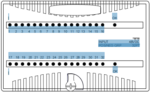
Product Description Discrete input modules IC200MDL640 and BXIOID1624 provide two groups of 8 discrete inputs. Discrete input module IC200MDL650 (shown below) and BXIOIX3224 provide four groups of 8 discrete inputs.
GE IC200MDL650 VersaMax 24VDC Input Modules
Inputs in each group can be either positive logic inputs that receive
current from input devices and return the current on the common, or
negative-logic inputs that receive current from the common and return
current to the input device. Input devices are connected between the
input terminals and common terminals.
OK
OK
1 2 3 4 5 6 7 8 9 10 11 12 13 14 15 16
I
I
17 18 19 20 21 22 23 24 25 26 27 28 29 30 31 32
INPUT 48VDC
POS/NEG GRP 32PT
Note: Negative-logic functionality requires module version
IC200MDL650C / BXIOID3225C or higher.
Power for module operation comes from the backplane.
Intelligent processing for the module is performed by the CPU or NIU.
LED Indicators
Individual green LEDs indicate the on/off state of each input point.
The green OK LED is on when backplane power is present to the
module.
Preinstallation Check
Carefully inspect all shipping containers for damage. If any equipment
is damaged, notify the delivery service immediately. Save the damaged
shipping container for inspection by the delivery service. After
unpacking the equipment, record all serial numbers. Save the shipping
containers and packing material in case it is necessary to transport or
ship any part of the system.
(total response time is 1.5ms).
Installation in Hazardous Locations
EQUIPMENT LABELED WITH REFERENCE TO CLASS I,
GROUPS A, B, C & D, DIV. 2 HAZARDOUS LOCATIONS IS
SUITABLE FOR USE IN CLASS I, DIVISION 2. GROUPS A, B, C,
D OR NON-HAZARDOUS LOCATIONS ONLY
WARNING - EXPLOSION HAZARD - SUBSTITUTION OF
COMPONENTS MAY IMPAIR SUITABILITY FOR CLASS I,
DIVISION 2;
WARNING - EXPLOSION HAZARD - WHEN IN HAZARDOUS
LOCATIONS, TURN OFF POWER BEFORE REPLACING OR
WIRING MODULES; AND
WARNING - EXPLOSION HAZARD - DO NOT DISCONNECT
EQUIPMENT UNLESS POWER HAS BEEN SWITCHED OFF OR
THE AREA IS KNOWN TO BE NONHAZARDOUS.
Module Characteristics
Points IC200MDL640. BXIOIS1624: 16 (2 groups of 8)
IC200MDL650. BXIOID3224: 32 (4 groups of 8)
Module ID IC200MDL640. BXIOIS1624: FFFF8008
IC200MDL650. BXIOID3224: 80088008
Isolation: User input to logic (optical) and frame ground: 250VAC
continuous; 1500VAC for 1 minute
Group to Group: 250VAC continuous; 1500VAC for 1
minute
Point to point: None
LED indicators One LED per point shows individual point ON/OFF status
OK LED indicates backplane power is present
Backplane current
consumption (5V
output)
IC200MDL640. BXIOIS1624: 25mA maximum
IC200MDL650. BXIOID3224: 50mA maximum
External power supply None
Thermal derating IC200MDL640. BXIOIS1624: No derating
IC200MDL650. BXIOID3224: See chart
Configuration
parameters
Input response times
Input Characteristics
Input voltage 0 to +30VDC,+24VDC nominal
On state voltage +15 to +30VDC
Off state voltage 0 to +5VDC
On state current
Off state current
2.0 to 5.5mA
0 to 0.5mA
On response time
Off response time
0.5ms maximum
Configurable filter
time
0 ms, 1.0ms (default), or 7.0ms
Input impedance 10kOhms maximum
Product Revision History
Rev Date Description
IC200MDL640K
IC200MDL650K
December 2011 Label change. No changes to
features, performance or
compatibility.
IC200MDL640G / BXIOID1624G
IC200MDL650G / BXIOID3224G
October 2008 Updated Power Supply OK
signal circuitry.
IC200MDL640F / BXIOID1624F
IC200MDL650F / BXIOID3224F
April 2005 Improvement to latching
mechanism
IC200MDL640E
IC200MDL650E
April 2004 Changed to V0 plastic for
module housing.
BXIOID1624E
BXIOID3224E
January 2004 Changed to V0 plastic for
module housing. ATEX
approval for Group 2
Category 3 applications.
IC200MDL640D
IC200MDL650D
January 2004 ATEX approval for Group 2
Category 3 applications.
IC200MDL640C / BXIOID1624C
IC200MDL650C / BXIOID3224C
November 1999 Added operation with
negative logic inputs.
IC200MDL640A / BXIOID1624A
IC200MDL650A / BXIOID3224A
September
1998
Original product
Field Wiring Terminals
Terminal Connection Terminal Connection
A1 Input 1 B1 Input 17 *
A2 Input 2 B2 Input 18 *
A3 Input 3 B3 Input 19 *
A4 Input 4 B4 Input 20 *
A5 Input 5 B5 Input 21 *
A6 Input 6 B6 Input 22 *
A7 Input 7 B7 Input 23 *
A8 Input 8 B8 Input 24 *
A9 Input 9 B9 Input 25 *
A10 Input 10 B10 Input 26 *
A11 Input 11 B11 Input 27 *
A12 Input 12 B12 Input 28 *
A13 Input 13 B13 Input 29 *
A14 Input 14 B14 Input 30 *
A15 Input 15 B15 Input 31 *
A16 Input 16 B16 Input 32 *
A17 Inputs 1-8 Common B17 Inputs 17-24
Common *
A18 Inputs 9-16
Common
B18 Inputs 25-32
Common *
* Inputs available on 32-point modules only.
The 32 inputs form groups of 8. Each group has a common connection.
Each group may be wired for positive or negative logic inputs. Note:
Negative-logic functionality requires module version -C or higher.
For the 16-point modules, if additional bussed terminals are needed, the B
terminals can be made available using a shorting bar. The shorting bar has
a maximum current-carrying capacity of 2 Amps per point. See the
VersaMax I/O Modules Manual, GFK-1504 for information about using a
shorting bar.
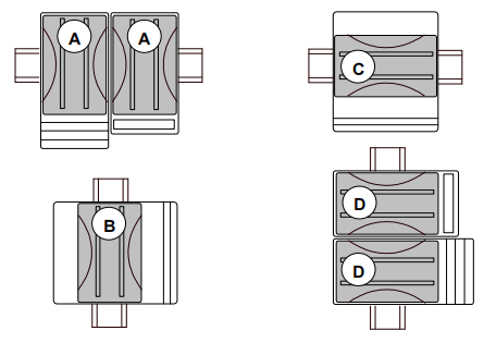
Wiring Connections for Carriers with Two Rows of Terminals
Row B connections shown below are for 32-point modules only.
1 2 3 4 5 6 7 8 9 11 12 13 14 15 16 17 18
1 2 3 4 5 6 7 8 9 11 12 13 14 15 16 17 18 10
10
I17 I18 I19 I20 I21 I22 I23 I24 I25 I26 I27 I28 I29 I30 I31 I32
I1 I2 I3 I4 I5 I6 I7 I8 I9 I10 11 I12 I13 I14 I15 I16
B
A
+ -
(+) (-)
+ -
(+) (-)
+ -
(+) (-)
+ -
(+) (-)
-
(+)
-
(+)
-
(+)
-
(+)
Wiring Connections for Carriers with Three Rows of Terminals
Side B connections shown below are for 32-point modules only.
| User name | Member Level | Quantity | Specification | Purchase Date |
|---|


- other
- LTI Drives
- ADLINK
- Beckhoff
- Other Brands
- AMAT
- Iba
- PEPPERL+FUCHS
- Aerotech
- WATLOW
- MAN
- ADVANCED
- Abaco
- YOKOGAWA
- KOLLMORGEN
- MEGGITT
- kong-sberg
- METSO
- Motorola
- NI
- OEMAX
- RELIANCE
- scanlab
- schneider
- uniop
- Vibro-Meter
- Honeywell
- Rolls-Royce
- MOOG
- GE
- B&R
- Woodward
- Yaskawa
- xYCOM
- Siemens
- Emerson
- HIMA
- Bently
- ZYGO
- FOXBORO
- OMACO
- PROSOFT
- ENTERASYS
- TRICONEX
- Parker
- Lenze
- KEBA
- Alstom
- CTI
- ABB
- A-B

-
 ADLINK PCI-9112/cPCI-9112 multifunctional acquisition card
 -
 ADLINK PCI-8102 Two Axis Pulse Motion Control Card
 -
 ADLINK PCI-9812/PCI-9810 synchronous 4-channel high-speed acquisition card
 -
 ADLINK PCI-7200/cPCI-7200 high-speed digital I/O board
 -
 ADLINK MXE-1000 series fanless embedded machine
 -
 ADLINK IMB-T10 Mini ITX Industrial Motherboard
 -
 ADLINK HSL Distributed High Speed I/O System
 -
 ADLINK PXI/DAQ/DAQe-2500 series multifunctional analog output DAQ card
 -
 ADLINK PXI/DAQ/DAQe-2200 series multifunctional data acquisition card
 -
 ADLINK ETX-AT ETX Core Computer Module
 -
 ADLINK ACL-7225 ISA 16 channel relay output+16 channel isolated digital input card
 -
 ADLINK DAQ-2000 series synchronous acquisition card
 -
 ADLINK NuPRO-E330 PICMG 1.3 full-length industrial motherboard (SHB)
 -
 ADLINK ACL-8112 series multifunctional ISA acquisition card
 -
 ADLINK USB-2405 24 bit dynamic signal acquisition module
 -
 ADLINK PXIS-3320 15 slot 6U PXI chassis
 -
 ADLINK PCIe GIE7x series acquisition card
 -
 ADLINK PCIe-7856/PCIe-7853 Distributed Motion and IO Main Controller PCIe Acquisition Card
 -
 ADLINK PCI-6308 series isolated analog output board
 -
 ADLINK PCI-7432 Isolated Digital I/O Acquisition Card
 -
 ADLINK NuPRO-E72 PICMG 1.3 Full length Industrial SHB Single Board Computer
 -
 ADLINK MXE-5400 series fanless embedded industrial computer
 -
 ADLINK M-322 Industrial ATX Motherboard
 -
 ADLINK IMB-M43H Industrial ATX Motherboard
 -
 ADLINK IMB-M42H Industrial ATX Motherboard
 -
 ADLINK i915GV-INA ATX motherboard
 -
 ADLINK ETX-NR667 Embedded ETX Standard Computer Module
 -
 ADLINK ETX-BT (PATA to SATA version) User Manual
 -
 ADLINK CM1-BT1 PC/104 Single Board Computer
 -
![ADLINK cPCI-8217 [R] 3U CompactPCI VGA/LCD Display Module](https://aosspic10001.websiteonline.cn/hkw632bc8/image/image_aJXQRn.png) ADLINK cPCI-8217 [R] 3U CompactPCI VGA/LCD Display Module
ADLINK cPCI-8217 [R] 3U CompactPCI VGA/LCD Display Module -
 ADLINK AmITX-SL-G Mini ITX Embedded Motherboard
 -
 ADLINK AmITX-AL-I ultra-thin Mini ITX industrial motherboard
 -
 ADLINK NuPRO-E315 Full length PICMG 1.3 Industrial SHB Single Board Computer
 -
 ADLINK NuPRO-842 Full length PICMG 1.0 PCI/ISA Industrial Single Board Computer
 -
 ADLINK NuPRO-900A PICMG 1.2 ePCI-X Dual Xeon Industrial System Motherboard (SHB)
 -
 ADLINK cPCI-6910 series 6U CompactPCI single board computer
 -
 ADLINK cPCI-6860A 6U CompactPCI dual core single board computer with cPCI-R6860A rear adapter board
 -
 ADLINK cPCI-8168 6U CompactPCI Eight Axis Motion Control Card
 -
 ADLINK NuPRO-E340 PICMG 1.3 Industrial SHB motherboard
 -
 ADLINK NuPRO-A40H Full length PICMG1.0 Industrial Single Board Computer (SBC)
 -
 ADLINK NuPRO-852 Full length PICMG1.0 Industrial Single Board Computer
 -
 ADLINK NuPRO-841 Full length Industrial SBC
 -
 ADLINK NuPRO-590/591/592 series Socket7 full-length industrial SBC
 -
 ADLINK MXE-5500 series fanless embedded industrial computer
 -
 ADLINK MXE-200/200i Fanless Embedded Machine
 -
 ADLINK cPCI-6770 series CompactPCI CPU board
 -
 ADLINK NuPRO-A301 standard PICMG 1.0 full-length industrial SBC single board computer
 -
 ADLINK NuPRO-965 PICMG 1.3 SHB Express Full length Industrial Motherboard
 -
 ADLINK NuPRO-935A Full length PICMG1.0 Industrial Single Board Computer
 -
 ADLINK NuPRO-865 Full length Single Board Computer
 -
 ADLINK NuPRO-840 DV/LV Full Length PICMG Industrial Single Board Computer
 -
 ADLINK NuPRO-770 series full-length industrial single board computer
 -
 ADLINK NuPRO-595 series half length Socket 7 industrial motherboard
 -
 ADLINK cPCI-6840 series 6U CompactPCI single board computer
 -
 Foxboro 43AP series pneumatic indicator controller (PSS 3-1B3 A)
 -
 ADLINK cPCI-3720 Series 3U Low Power CompactPCI Single Board Computer
 -
 ADLINK NuPRO-E47, PICMG 1.3 full-length industrial SHB system motherboard
 -
 ADLINK NuPRO-E43 PICMG 1.3 full-length system motherboard
 -
 ADLINK NuPRO-780 series full-length industrial CPU board
 -
 ADLINK cPCI-6965 series 6U CPCI single board computer
 -
 ADLINK USB/LPCI/LPCIe-3488A GPIB interface card
 -
 Rittal SK 3241.700 Blue e+Fan Filter Unit
 -
 ADLINK cPCI-8168 6U CompactPCI 8-Axis Motion Control Card
 -
 ADLINK PCIe PXIe-8638 PCIe to PXIe Bus Expansion Kit
 -
 ADLINK PCIe GIE7x series acquisition card
 -
 ADLINK PCIe-7396 96 96 channel TTL digital IO card
 -
 ADLINK PCI/MPC/PXI-8164 Three in One Motion Control Card
 -
 ADLINK PCI-8154 Four Axis Pulse Motion Control Card
 -
 ADLINK PCI-8134 Four Axis Servo/Stepper Motion Control Card
 -
 ADLINK NuPRO-E42 PICMG1.3 full-length SHB motherboard
 -
 ADLINK MXC-6600 series high-performance fanless extended industrial computer
 -
 ADLINK MXC-6000 series embedded industrial control computer
 -
 ADLINK MXC-2300 series fanless expandable embedded industrial computer
 -
 ADLINK MCM-204 Independent Ethernet DAQ User Manual
 -
 ADLINK MCM-100/102 Edge IoT Platform for Machine Condition Monitoring User’s Manual
 -
 ADLINK MXC-6400 series sixth generation Core Fanless Scalable Industrial Control Computer
 -
 ADLINK Matrix Full Series Fanless Embedded Industrial Control Computers
 -
 ADLINK GIE64+4-channel PoE Gigabit Vision Capture Card
 -
 Honeywell UMS Security System Troubleshooting Guide
 -
 Honeywell Expert Series-C I/O Module
 -
 ADLINK EOS-1200 Embedded Vision Host
 -
 ADLINK DLAP-5200 series high-performance fanless AI industrial computer
 -
 ADLINK DLAP-4000 series embedded industrial control computer
 -
 ADLINK Matrix MXC-2000 Series Fanless Industrial Control Computer Specification
 -
 ADLINK DAQ -/DAQE -/PXI-2000 Series Multi functional Synchronous Acquisition Card
 -
 ADLINK cPCI-6520 6U CompactPCI Single Board Computer
 -
 ADLINK CM1-86DX3 PC/104 Single Board Computer
 -
 Honeywell DC1000 series PID temperature controller
 -
 ALSTOM MiCOM C264 Modular Substation Controller
 -
 EMERSON AMS 2140 Mechanical Health Analyzer
 -
 ADLINK NuPRO-E320 PICMG1.3 Full length Industrial Motherboard
 -
 ADLINK NuPRO-800 Series Full length Industrial SBC User Manual
 -
 ADLINK NuPRO-598 Industrial Single Board Computer
 -
 ADLINK MXC-6300 Fanless Embedded Industrial Control Computer
 -
 ADLINK Express-BASE7 User Manual
 -
 ADLINK DLAP-211 Series Fanless Edge AI Platform Specification Manual
 -
 ADLINK PCI/LPCI/LPCIe/cPCI-723X series 32 channel isolated digital I/O card
 -
 ADLINK cPCI-6965 series 6U CompactPCI single board computer
 -
 ADLINK NuDAQ 7200 series high-speed digital I/O board
 -
 Linghua ADLINK DLAP Deep Learning Acceleration Platform Product Manual
 -
 DEIF TCM-2 thyristor control module
 -
 Installation Manual for DEIF MVR-200 Series Medium Voltage Protection Device
 -
 DEIF MDR-2 multifunctional differential relay
 -
 DEIF AOM-1 Analog Output Module
 -
 DEIF AGI 400 series industrial/marine touch screen
 -
 Installation Manual for DEIF BRW-1 Marine Wing Bridge Instrument
 -
 DEIF AGC200 Quick Start Guide
 -
 DEIF AGC Multi line 2 Generator Set ControllerProduct basic information
 -
 ABB SPA-ZC 400 Ethernet Gateway Installation and Debugging Manual
 -
 ABB REM 543/545 motor generator protection device
 -
 DEIF PPU 300 controller
 -
 DEIF Delomatic 4 Offshore/Ocean Platform Dedicated Generator Power Management System DM-4
 -
 DEIF Delomatic Modular Generator Set Integrated System
 -
 DEIF AGC-4 Mk II Generator Set Controller
 -
 DEIF AGC-4 diesel generator set integrated controller
 -
 DEIF Multi line 2 Series PPU Unit Power Management (PPM) Operation Manual
 -
 DEIF Multi line 2 V2.4X Installation Manual
 -
 Beckwith M-6280 Digital Capacitor Bank Controller
 -
 Beckwith M-3311 Transformer Protection Relay
 -
 Beckwith M-3311A Transformer Integrated Protection Device
 -
 Beckwith M-3310 Transformer Integrated Protection Device Specification
 -
 Beckwith M-0359 Syncrocloser Check Plus Application Guide for Synchronous Calibration Relay
 -
 Beckwith M-0293A On Load Tap changer Controller Application Guide
 -
 DEIF GPU-3 Synchronous/Asynchronous Generator Integrated Microcomputer Protection Controller
 -
 Installation Instructions for DEIF PPM-3
 -
 Beckwith M-3520 distributed power grid connected comprehensive protection device
 -
 Beckwith M-3430 generator comprehensive protection device
 -
 Beckwith M-2293B adapter panel

K-JIANG

Add: Jimei North Road, Jimei District, Xiamen, Fujian, China
Tell:+86-15305925923