
K-WANG


- Telephone:+86-15305925923
- contacts:Mr.Wang
- Email:wang@kongjiangauto.com
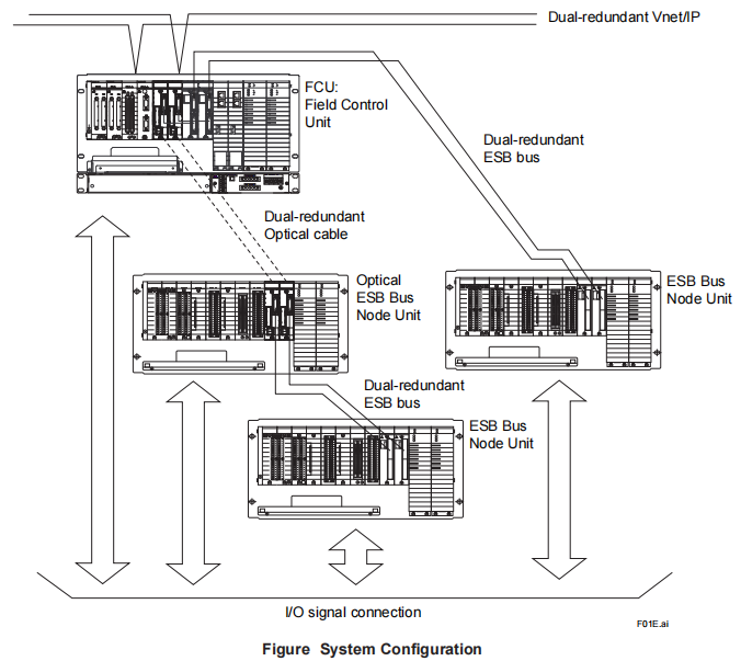
The FIO (Fieldnetwork I/O) System is connected to the Field Control Unit (FCU) via an ESB, optical ESB, or ER
bus.
The Field Control Unit (AFV30/AFV40) is connected to an ESB Bus Node Unit (ANB10) or an Optical ESB
Bus Node Unit (ANB11). The Field Control Unit (AFV10) is connected to an ESB Bus Node Unit (ANB10) or
an ER Bus Node Unit (ANR10).
A node unit consists of a power supply module, a bus interface module, and input/output modules that are installed
in a base unit. The power supply module, bus interface module, and input/output modules can be configured
redundantly.
The Unit for Optical ESB Bus Repeater Module (ANT10U) can be used to connect the optical ESB bus in a chain or
star configuration.
The following shows a system configuration example
YOKOGAWA GS33K50F10-50E FIO System Overview
Installation Environment
Item Specification
Ambient temperature
Normal operating
0 to 50 °C (AFV30, AFV40, ACB51. AFV10)
0 to 60 °C (ANB10, ANB11, ANT10U, ANR10)
(-20 to 70 °C temperature option for ANB10, ANB11, ANT10U, ANR10)
Transporting/storing
-20 to 60 °C (avoid direct sunlight.)
(-40 to 85 °C temperature option for ANB10, ANB11, ANT10U, ANR10,
avoid direct sunlight)
Ambient humidity Normal operating 5 to 95 %RH (should have no condensation.)
Transporting/storing 5 to 95 %RH (should have no condensation.)
Ambient temperature
change rate
Normal operating Within ±10 °C/h
Transporting/storing Within ±20 °C/h
Power supply
Voltage range
100 to 120 V AC ±10 %
220 to 240 V AC ±10 %
24 V DC ±10 %
Frequency 50/60 ±3 Hz
Distortion factor 10 % or less
Peak value 125 V or more (100 V system)
274 V or more (220 V system)
Instantaneous power
failure 20 ms or less (when receiving rated AC voltage)
DC power supply ripple
rate 1 % p-p or less
Grounding 100 ohms or less, Independent grounding
Dust 0.3 mg/m3
or less
Corrosive gas ANSI/ISA S71.04 G2 (standard) (ANSI/ISA S71.04 G3 option)
Vibration
Continuous vibration Displacement amplitude 0.25 mm or less (1 to 14 Hz)
Acceleration 2.0 m/s2
or less (14 to 100 Hz)
Earthquake Acceleration 4.9 m/s2
or less
Transport vibration Horizontal 4.9 m/s2
or less, vertical 9.8 m/s2
or less (packed state)
Shock Transport shock Horizontal 49.0 m/s2
, vertical 98.0 m/s2
(packed state)
Noise
Electric field
3 V/m or less (26 MHz to 1.0 GHz)
3 V/m or less (1.4 to 2.0 GHz)
1 V/m or less (2.0 to 2.7 GHz)
Magnetic field 30 A/m or less (AC), 400 A/m or less (DC)
Static electricity 4 kV or less (contact discharge), 8 kV or less (aerial discharge)
Altitude 2000 m or less
*1: When a ER Bus Node Unit is used under the temperature environment (-20 to 0 °C), it requires 10 minutes to start up
EB501 after turning on the power switch.
When the following modules are installed in ESB
l ESB bus/Optical ESB bus
When using Field Control Unit (AFV30/AFV40)
Application
An ESB bus or an optical ESB bus is an input/output communication bus that connects the ESB bus node unit or
optical ESB bus node unit to the intelligent part of the FCS.
Communication Specifications
Connectable Units: ESB Bus Node Unit (ANB10), Optical ESB Bus Node Unit (ANB11), and Unit for Optical ESB
Bus Repeater Module (ANT10U)
Number of Connectable Units: The number of ESB bus node units and optical ESB bus node units that can be
connected to the ESB bus varies depending on the selected database.
Units for Optical ESB Bus Repeater Module (ANT10U) are not included in the number of connectable units.
Field Control
Unit Database
Total Number of ESB
Bus and Optical
ESB Bus Node Units
Connected per FCU (*1)
AFV30 (*2)
AFV40 (*2) (*3)
Control Function for Field Control Station (LFS1700) Max. 3
Control Function for Field Control Station (LFS1700) plus Node Expansion Package
(LFS1750-V1) Max. 9
Control Function for Field Control Station (LFS1700) plus Node Expansion Package
(LFS1750-V2) Max. 13
*1: ESB Bus Node Unit (ANB10), Optical ESB Bus Node Unit (ANB11)
*2: To connect the ESB bus node unit and optical ESB bus node unit to the FCU (AFV30/AFV40), install the ESB Bus
Coupler Module (EC401 or EC402) in slots 7 and 8.
EC401 can be connected a maximum of nine Node Units (ANB10or ANB11).
EC402 can be connected a maximum of nine Node Units (ANB10or ANB11) on the upper and lower sides, respectively.
The sum of the total number of Node Units (ANB10 or ANB11) per FCU should not exceed the specified number.
*3: The maximum number of ESB bus node units, optical ESB bus node units, and units for optical ESB bus repeater module
that can be installed in a single cabinet is 11 for AFV40.
Transmission Path Specifications
Network Topology: Bus topology
Transmission Path Redundancy: Available
Transmission Speed: 128 megabits per second
Transmission Cable: Dedicated cable (YCB301), a
ER bus
When using Field Control Unit (AFV10)
Application
An input/output communication bus used in a standard FCS for FIO. The ER bus connects local nodes or Compact
Field Control Unit for FIO to ER Bus Node Unit.
Communication Specifications
Field Control
Unit Database ER Bus Node Units
Connected per FCU (*1)
Total Number of ESB
Bus Node Units and
ER Bus Node Units
Connected per FCU (*1)
AFV10
Control Function for Field Control Unit LFS1500 Max. 3 Max. 3
Control Function for Field Control Unit LFS1500
plus Application Capacity Expansion Package
(LFS1550)
Max. 14 (*2) Max. 14
*1 ESB Bus Node Units(ANB10), ER Bus Node Units(ANR10)
*2: Up to 8 ER Bus Node Units per ER bus can be connected.
Note: Number of ER bus: Max. 4 per FCU
Transmission Path Specifications
Network Topology: Bus topology
Transmission Path Redundancy: Available
Transmission Speed: 10 megabits per second
Transmission Cable: Coaxial cable (YCB141. YCB311). Use YCB147/YCB149 Bus Adapter Unit to connect a
YCB141 cable to a YCB311 cable. One grounding unit (YCB117) per segment (*1) should be used when
connecting YCB311 cable.
Transmission Distance:
YCB141: Max.185 m
When mixing YCB141 and YCB311:
Length of YCB141 + (185/500) x Length of YCB311 ≤ 185
Number of Bus Adapter Units: Max. 4 per segment (*1)
General-purpose Ethernet Repeater:
The total transmission distance is limited by the number of repeaters.
L ≤ 4 - 0.5 × n
L: total transmission distance (km)
n: the number of the general-purpose Ethernet repeater (Max. 4 repeaters)
*1: If repeaters are used on ER bus, each part of the ER bus segregated by a repeater is referred to as a segment.
Regulatory Compliance
For the detailed information of following standards, see “System Overview” (GS 33K01A10-50E) and GS on each
product.
Safety Standards
[CSA]
[CE Marking] (*1)
[EAC Marking] (*1)
EMC Conformity Standards
[CE Marking] (*1)
[EAC Marking] (*1)
[RCM]
[KC Marking]
Standards for Hazardous Location Equipment
[CSA Non-Incendive]
Field Control Unit (for Vnet/IP and FIO)
The following types of Field Control Unit (for Vnet/IP and FIO) are available.
AFV30S: Field Control Unit (for Vnet/IP and FIO, 19” Rack Mountable Type)
AFV30D: Duplexed Field Control Unit (for Vnet/IP and FIO, 19” Rack Mountable Type)
AFV40S: Field Control Unit (for Vnet/IP and FIO, with Cabinet)
AFV40D: Duplexed Field Control Unit (for Vnet/IP and FIO, with Cabinet)
For more detail, refer to “Field Control Unit (for Vnet/IP)” (GS 33K50E10-50E) and (GS 33K50E20-50E).
AFV10S: Field Control Unit (for Vnet/IP, for FIO, 19-inch rack mountable)
AFV10D: Duplexed Field Control Unit (for Vnet/IP, for FIO, 19-inch rack mountable)
For more detail, refer to “Field Control Unit (for Vnet/IP)” (GS 33K50E30-30E).
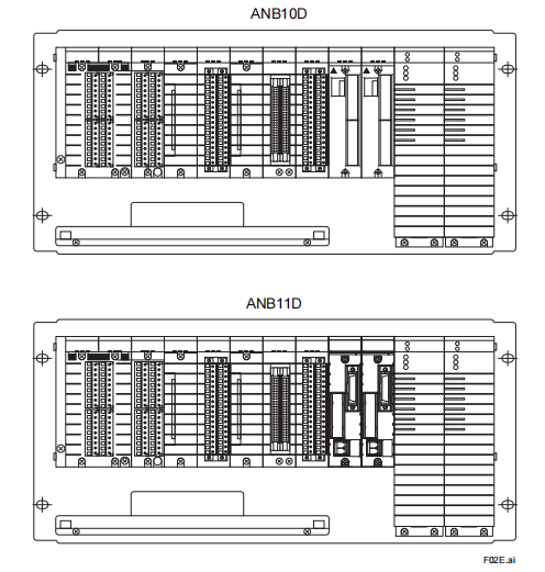
l Node Units
Power Supply Modules, Bus Interface Modules, and I/O Modules (FIO) are installed in a Node Unit.
The following types of Node Units are available, depending on the configuration, being either single/dual-redundant
bus or ESB BUS/Optical ESB Bus/ER Bus:
ANB10S: Node Unit for Single ESB Bus (Rack Mounting)
ANB10D: Node Unit for Dual-Redundant ESB Bus (Rack Mounting)
ANB11S: Node unit for Single ESB Bus with Optical Repeater (Rack Mounting)
ANB11D: Node unit for Dual-Redundant ESB Bus with Optical Repeater (Rack Mounting)
For more details, refer to “Node Units (for FIO)” (GS 33K50F20-50E) and (GS 33K50F30-50E).
ANR10S: Node Unit for Single ER Bus (Rack Mounting)
ANR10D: Node Unit for Dual-Redundant ER Bus (Rack Mounting)
For more details, refer to “Node Units (for FIO)” (GS 33K50F21-50E)
| User name | Member Level | Quantity | Specification | Purchase Date |
|---|


- other
- ADLINK
- LTI Drives
- Other Brands
- AMAT
- Iba
- PEPPERL+FUCHS
- Aerotech
- WATLOW
- MAN
- ADVANCED
- Abaco
- YOKOGAWA
- KOLLMORGEN
- MEGGITT
- kong-sberg
- METSO
- Motorola
- NI
- OEMAX
- RELIANCE
- scanlab
- schneider
- uniop
- Vibro-Meter
- Honeywell
- Rolls-Royce
- MOOG
- GE
- B&R
- Woodward
- Yaskawa
- xYCOM
- Siemens
- Emerson
- HIMA
- Bently
- ZYGO
- FOXBORO
- OMACO
- PROSOFT
- ENTERASYS
- TRICONEX
- Parker
- Lenze
- KEBA
- Alstom
- CTI
- ABB
- A-B

-
 Beckwith M-3311A Transformer Integrated Protection Device
 -
 Beckwith M-3425A Generator Integrated Protection Device Manual
 -
 Basler BE1-27/BE1-59/BE1-27/59 undervoltage/overvoltage relay
 -
 Basler AVC63-12/AVC125-10 excitation voltage regulator
 -
 Basler L301kc Color Three Line Array Camera Operation Manual
 -
 Basler CBS 212A Current Enhanced Excitation System
 -
 Basler BE3-25 synchronous check relay
 -
 Operation Manual for Basler BE1-32R/BE1-32O/U Direction Power Relay
 -
 Basler Electric PRS-250 Veri Sync Synchronous Relay
 -
 Basler Pilot Series Area Array Industrial Camera piA2400-17gc
 -
 Basler BE1-11g comprehensive protection device for generator
 -
 Basler VR63-4C/UL Analog Excitation Voltage Regulator
 -
 Basler BE1-DFPR distribution feeder protection relay
 -
 Basler CBS310/CBS320 current strong excitation system
 -
 Basler UFOV250A/UFOV260A Low Frequency Overvoltage Module
 -
 Basler MVC104/MVC108/MVC232 manual voltage control device
 -
 Basler XR2002/XR2002F PMG excitation regulator
 -
 Basler DECS-400 Digital Excitation Control System
 -
 Basler DGC-2020 Digital Generator Set Controller
 -
 Basler MVC-300 Electronic Manual Excitation Controller
 -
 Basler MVC-104/MVC-108/MVC-232 manual excitation controller
 -
 Basler SSR32-12/SSR63-12/SSR125-12 Static Excitation Voltage Regulator
 -
 Basler SR4A/SR8A Analog Excitation Voltage Regulator
 -
 Basler BE2000E Digital Excitation Voltage Regulator
 -
 Basler DECS-2100 Digital Excitation System
 -
 Basler BE1-851 Overcurrent Protection Device Manual
 -
 Basler APR 63-5 Voltage Regulator
 -
 Basler BE1-FLEX Integrated Protection Control System
 -
 Basler BE1-700V digital voltage protection relay
 -
 Basler BE1-87B high impedance bus differential relay
 -
 Basler BE1-40Q demagnetization relay
 -
 Basler BE1-60 Voltage Balance Relay
 -
 Basler BE1-47N negative sequence voltage phase sequence relay
 -
 Basler BE1-81O/U digital frequency relay
 -
 Basler BE1-11f Feedline Integrated Protection Device Manual
 -
 Basler DECS-250 Digital Excitation Control System
 -
 Basler DECS-100 Digital Excitation Control System
 -
 Basler BE1-BPR Circuit Breaker Protection Relay
 -
 Basler BE1-50/51B-255 overcurrent relay
 -
 Basler BE1-25 synchronous check relay
 -
 Basler BE1-51 microcomputer time limited overcurrent relay
 -
 Basler DECS-300 Digital Excitation Control System
 -
 Mitsubishi MELSEC-F FX series programmable controllers
 -
 Hirschmann cSCALE Mobile Machinery Modular Controller
 -
 Hirschmann OZD Profi G12DU/G12DK/G12DE ATEX1 PROFIBUS Fiber Optic Repeater Manual
 -
 Hirschmann OCTOPUS OS20/OS24 Network Managed IP65/IP67 Industrial Switch Installation Manual
 -
 Hirschmann RS20/RS22/RS30/RS32/RS40 Series Industrial Rail Switch Installation Manual
 -
 Hirschmann EAGLE One Industrial Ethernet Firewall Installation Manual
 -
 Hirschmann MACH102 Series Industrial Switch Installation Manual
 -
 Hirschmann MS20/MS30 Modular Industrial Switch Installation Manual
 -
 Hirschmann BRS20/22/30/32/40/42/50/52 Series BOBCAT Industrial Rail Switch Installation Manual
 -
 Hirschmann RSB20 Basic Series Industrial Rail Switch Installation Manual
 -
 Hirschmann RS20 Basic Series Industrial Ethernet DIN-Rail Switches
 -
 BECKHOFF EP20xx/EP28xx IP67 EtherCAT Box Digital Output Module
 -
 BECKHOFF EL5102 Incremental Encoder Terminal Manual
 -
 BECKHOFF CU8803-000x CP Link4 Launch Box Operation Manual
 -
 Beckhoff CU20xx/CU22xx Industrial Unmanned Switch Manual
 -
 BECKHOFF AMP8000 Distributed Servo System Operation Manual
 -
 BECKHOFF EL2911/EL2911-2200 TwinSAFE Safety Potential Supply Terminal Manual
 -
 BECKHOFF EL600x/EL602x series EtherCAT serial port terminal module
 -
 BECKHOFF CP6700-0001-0050/0060 Integrated Machine Manual
 -
 BECKHOFF CP70xx Series Control Panel Installation and Operation Manual
 -
 BECKHOFF CP29xx Cabinet Mounted Industrial Touch Panel Official Operation Manual
 -
 Beckhoff C6650-0060 Control Cabinet Industrial PC
 -
 Beckhoff BK series K-bus to EtherCAT coupler
 -
 Beckhoff CX20x0 Series Embedded Industrial Control Computer Manual
 -
 Beckhoff CP77xx Series Industrial Panel PC Installation and Operation Manual
 -
 Beckhoff EL41xx Series 16 Bit Analog Output Terminal Manual
 -
 Beckhoff C63xx-0020 series control cabinet industrial PC
 -
 Beckhoff C6920-0060 Control Cabinet Industrial PC
 -
 Beckhoff CU8800-0010 USB transmitter extender (TX)
 -
 Beckhoff AX2000 series digital servo amplifier
 -
 Beckhoff AX8000 Modular Multi Axis Servo System
 -
 Beckhoff CP27xx Embedded Panel PC User Manual
 -
 Beckhoff CP69xx Industrial Embedded Control Panel
 -
 Beckhoff CP60xx Embedded Industrial Control Panel
 -
 Beckhoff CP72xx series panel PC official installation, operation, configuration, maintenance, and troubleshooting
 -
 Installation and Operation of Beckhoff CP78xx Series Control Panel
 -
 Beckhoff CP39xx series industrial touch control panel
 -
 Beckhoff CX8110 Embedded Industrial PC
 -
 Beckhoff CX50x0 series DIN rail embedded industrial PC
 -
 Beckhoff CP62xx series embedded panel PC
 -
 BECKHOFF C6030 Compact Industrial PC
 -
 UniOP ePAD32B/ePAD33B/ePAD33BT Industrial HMI
 -
 UniOP ePAD05&ePAD06 Industrial HMI
 -
 UniOP ePAD03/ePAD04 entry-level HMI
 -
 UniOP CP01R-04 Compact Industrial HMI
 -
UniOP BKDR-16 Industrial Human Machine Interface
-
 Beckwith M-3425A Generator Integrated Protection Relay
 -
 Basler DECS-200 Digital Excitation Control System
 -
 Basler DECS-250 Digital Excitation Control System Manual
 -
 HA-800 series AC servo drive
 -
 JUMO dTRANS p35 Pressure Sensor Operation Manual with IO Link Interface
 -
 KEBA XE 020 RFID Module
 -
 Honeywell SmartLine series transmitters
 -
 Eaton CROUSE-HINDS MTL MA30 RF and Surge Protector Operation Manual
 -
 Beckhoff EL31xx Series 16 Bit EtherCAT Analog Input Terminal Manual
 -
 BECKHOFF AX5000 series EtherCAT servo drive
 -
 BECKHOFF EL30xx Series 12 Bit Analog Input Terminal Manual
 -
 Beckhoff EL70x7 series stepper motor EtherCAT terminal manual
 -
 BECKHOFF CX52x0 Series Embedded Industrial PC Hardware Manual
 -
 BECKHOFF CX9000/CX9010 series embedded controllers
 -
 BECKHOFF AM8000/AM8500 Series Synchronous Servo Motor Operation Manual
 -
 BECKHOFF EL9xxx series EtherCAT system terminal
 -
 BECKHOFF EK110x/EK15xx series EtherCAT bus coupler
 -
 BECKHOFF CX51x0 Series Embedded PC Hardware Manual
 -
 BECKHOFF CX2100-0014 Embedded Power Unit User Manual
 -
 BECKHOFF CX1000 Series Modular Embedded Industrial PC Hardware Manual
 -
 BECKHOFF CP69xx series embedded industrial control panel usage instructions
 -
 Beckhoff C6030-0080 ultra compact industrial PC
 -
 IFM O3D series time-of-flight 3D industrial sensor usage instructions
 -
 Allen Bradley Guardmaster 440R series safety relay
 -
 OMRON SYSMAC CS1 Rack mounted Large and Medium sized PLC Selection
 -
 GE Multilin EPM9900P high-precision power quality analyzer
 -
 Automotive LC-4 series brushless DC driver
 -
 Doric NC500 Neuroscience Acquisition Host
 -
 Honeywell X-DCS2000/EN DIGITAL INTEGRATED SYSTEM MANAGER SYSTEM MANAGER
 -
 Kollmorgen SERVOSTAR600 (601~620) servo drive
 -
 ABB Totalflow X series differential pressure flow computer
 -
 ABB ACS6000 medium voltage frequency converter
 -
 OMRON NX502 model Sysmac platform machine controller hardware usage instructions
 -
 OMRON NX102 model hardware usage instructions
 -
 OMRON C200HX/HG/HE series rack mounted medium-sized PLC operating instructions
 -
 Azbil SDC35/SDC36 single circuit temperature controller
 -
 MITSUBISHI ELECTRIC HIGH PERFORMANCE, COST EFFICIENT GT25 SERIES
 -
 Eurotherm Mini8 Modular Temperature Control Controller
 -
 KEYENCE GC-1000/GC-1000R Safety Controller
 -
 SICK RLY3-EMSS300 safety relay

K-JIANG

Add: Jimei North Road, Jimei District, Xiamen, Fujian, China
Tell:+86-15305925923